STM32 is a microcontroller based on ARM cortex architechture. In previous tutorial we have seen how to use STM32 GPIO as output. In this tutorial we will expand this further, we will see how to use STM32 as input and based on this button input we will activate or deactivate a output. This tutorial explains what registers are used to use GPIO as input and how to program STM32 development board using Arduino IDE.
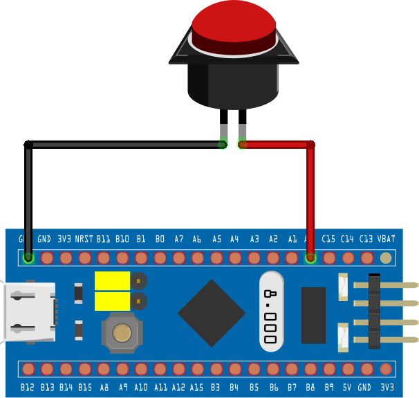
For this tutorial one of the GPIO pin connects to a push button to read input and PC13 will be used with a LED to turn it ON and OFF. The push button is connected to the PC14 and LED with PC13.
STM32 GPIO AS INPUT/OUTPUT:
Let’s take a look at the registers that’s responsible for making GPIO pins input. If you look at STM32 datasheet PC14 pin is in PORTC and LED is connected to PC13 which is also part of PORTC.
APB2 REGISTER:
We need to activate PORTC, to do this you need to write logic “1” to IOPC bit in APB2 register. Writing “1” to IOPC bit will enable the PORTC clock and thus activates the PORTC register
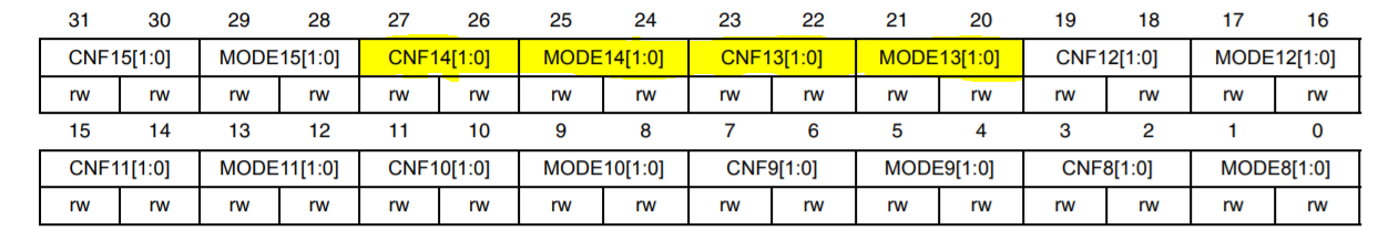
GPIO_CRH REGISTER:
GPIO_CRH register is responsible for activating individual pins of PORTC. We need to activate PC13 and PC14. The required bits are highlighted above. Each pin has two bits associated to it, where user can write logic 1 or 0 to these pins which determines the mode of operation ( input / output ).
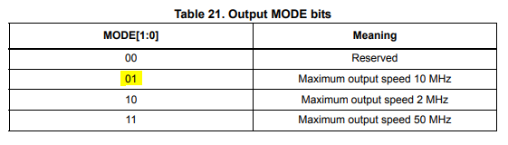
From this table we can deduce to make PC13 as output pin the registers CNF1 and CNF0 must be written 0 and 0. And MODE[1:0] bits of PC13 pins should be written as “0” and “1” as shown in the below table. Now, to use PC14 as input pin, associated bits CNF1 and CNF0 must be written 1 and 0. Also associated bit to PC14 in PCODR register must be written 1 to operate in Input pull-up mode.
GPIOC_ODR:
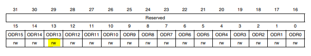
Now, PC14 and PC13 pins are configured as input an output. This GPIOC_ODR register is responsible for activating and deactivating output pins. All the bits in this register are Read/Write only. In order to activate any pin, we must write 1 to that particular bit. To activate PC13, ODR13 bit in this register should be written 1 and to deactivate it ODR13 should be written as 0.
GPIOC_IDR REGISTER:
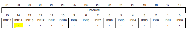
In this tutorial, when button connected with PC14 is pressed it will read “0” as it is configured in Input pull-up mode. The status of this input pin can be read using the GPIOC_IDR register. To read the status of PC14 input pin we should read the status of IDR14 bit in GPIOC_IDR register. This bit will read “1” when button is not pressed and “0” when button is pressed.
When input is “0” or button is pressed PC13 will written logic “1” and when button is released logic “0” should be written to deactivate the LED.
CODE:
const int inPin = PC14;             //PC14 as input pin
const int ledPin= PC13;             //PC13 as output LED
constint val;

void setup() {
  pinMode(ledPin, OUTPUT);
  pinMode(inPin, INPUT);
} Serial.begin(9600);

void loop() {
  val = digitalRead(inPin);
if(val==0)                            //if button is pressed
  digitalWrite(ledPin, HIGH);         //Activate the LED
else
  digitalWrite(ledPin, LOW);          //Deactivate the LED
}
Upload the code into the STM32 using FTDI and ARDUINO IDE. Hope this tutorial was useful to you. If you have any queries / doubts post them in the comments section below, we will address them.
Why all the diagrams and info about the stm32 registers and then show a standard (only change was the pin numbers) blink sketch. How do I access the stm32 registers directly from within the section ide?

 GPIO_CRH REGISTER:
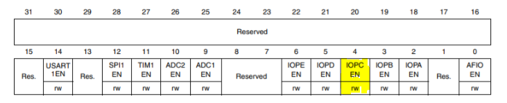
 GPIO_CRH register is responsible for activating individual pins of PORTC. We need to activate PC13 and PC14. The required bits are highlighted above. Each pin has two bits associated to it, where user can write logic 1 or 0 to these pins which determines the mode of operation ( input / output ).
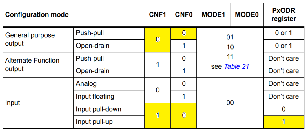


 Programming")
Why all the diagrams and info about the stm32 registers and then show a standard (only change was the pin numbers) blink sketch. How do I access the stm32 registers directly from within the section ide?