Sleep mode is a valuable feature in microcontrollers. With growing demand in portable embedded devices power management is an absolute necessary. To cater this power saving necessity microcontrollers are equipped with sleep mode functionality. This allows the programmer to disable different peripherals in a microcontroller. This will reduce the power consumed by microcontroller and thus enables the device to run longer.
Sleep modes in ATtiny85:
ATtiny85 microcontroller has three types of sleep mode. Each of these sleep mode allows different level of power saving functionality by allowing user to disable different set of peripherals in the controller.
Idle
ADC noise reduction
Power – down
Difference between three sleep modes:
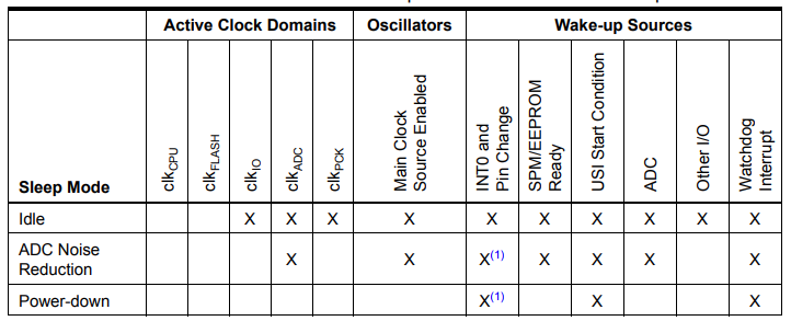
The above tabular column shows the key differences between different ATtiny85 sleep modes in terms of active clock domains, oscillators and wakeup sources. In idle mode clock to IO, ADC and PLL oscillator will be active. ADC noise reduction mode will only have active ADC clock. In power down mode all clock sources will be halted thus the power consumption will be lowest in this mode out of other sleep modes.
The Wake-up sources section in the tabular column shows the conditions that will wake the controller from its sleep condition. For example controller can be woken up only using INT0 and Pin change interrupts, USI ( serial communication ) start condition and Watch dog interrupts in Power-down sleep mode.
Do note that if interrupts occurs in the sleep mode, the MCU wakes up. The MCU requires four clock cycles to start up time. After this the interrupt subroutine will be executed. After the execution of this subroutine the system again goes to respective sleep mode. If user wants the controller to be stay awake upon reception of interrupts, the sleep mode need to be disabled in the interrupt sub routine.
SE – Bit 5 (Sleep Enable) must be written to one in order to put the controller to respective sleep mode. This bit must be written to one just when the user need the controller to sleep and should be cleared as soon controller wakes up to disable sleep mode. The SM1 and SM0 bits are used to select the sleep mode desired by the user. In this tutorial we are going to choose power-down sleep mode. After enabling the sleep enable bit SE, the instruction “sleep” follows to force the microcontroller to actually enter the sleep state. This is important as without the sleep instruction the microcontroller will not go to sleep even when SE bit is enabled.
Also it is important to configure the wakeup sources Interrupts, ADC, USI etc right before putting the controller to sleep state. Failing to do so will make the controller enter sleep mode without having any ways to wake them.
Steps to put the microcontroller to sleep mode:
Configure the appropriate wake up source that you intend to use to wake your microcontroller.
Select the corresponding sleep mode using bits SM1 and SM0 from MCUCR register.
Enable the Sleep enable bit SE in MCUCR register by writing 1 to it.
Pass the instruction “sleep” to microcontroller to actually enter the sleep state.
Use the wakeup source to wake the controller from sleep state.
Circuit diagram to demonstrate power-down sleep mode:
Best way to demonstrate working of sleep mode is by measuring the consumed current by controller between normal mode and sleep mode. But when using development board measuring current might not be a possibility. In those cases you can use the above setup to understand the sleep mode.
In the above circuit a LED is connected to PB1. A push button with PB2 to trigger pin change interrupt. The idea is to write instruction to light up the LED in PB1 and then put the controller to power-down sleep mode. We then use the push button to trigger pin change interrupt to wake up the controller from sleep.
Sample code for Power-down sleep mode in ATtiny85:
#include<avr/io.h>
#include<avr/interrupt.h>

ISR (PCINT0_vect)        // Interrupt service routine
{
  MCUCR&=~(1<<SE);      //Disabling sleep mode inside interrupt routine
}

void external_interrupt()
{
  DDRB |= (1<<PB1);     // set PB1 as output(LED)
  sei();                //enabling global interrupt
  GIMSK|= (1<<PCIE);    //Pin change interrupt enable
  PCMSK|=(1<<PCINT2);   //Pin change interrupt to 2nd pin PB2
}

void enters_sleep()
{
  MCUCR|=(1<<SM1);      // enabling sleep mode and powerdown sleep mode
  MCUCR|= (1<<SE);     //Enabling sleep enable bit
  __asm__ __volatile__ ( "sleep" "\n\t" :: ); //Sleep instruction to put controller to sleep
  //controller stops executing instruction after entering sleep mode
}

int main()
{
  external_interrupt();   // configuration for external interrupt
  PORTB|=(1<<PB1);
  enters_sleep();        // configuration for power down sleep mode
  PORTB&=~(1<<PB1);      //Controller will turn off the LED once it is woke up by interrupt
  while(1);
}
Try this out:
Put the ATtiny85 to sleep in Idle and ADC noise reduction mode and wake up using External interrupt.
best and clean explanation. i came here for information about attiny85 watchdog timer and sleep modes. i understand sleepmode but can’t find information about watchdog. thake you very much for information provided

 The above tabular column shows the key differences between different ATtiny85 sleep modes in terms of active clock domains, oscillators and wakeup sources. In idle mode clock to IO, ADC and PLL oscillator will be active. ADC noise reduction mode will only have active ADC clock. In power down mode all clock sources will be halted thus the power consumption will be lowest in this mode out of other sleep modes.
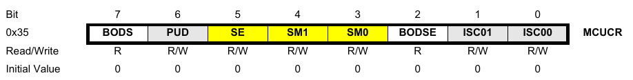
 The SM1 and SM0 bits are used to select the sleep mode desired by the user. In this tutorial we are going to choose power-down sleep mode. After enabling the sleep enable bit SE, the instruction “sleep” follows to force the microcontroller to actually enter the sleep state. This is important as without the sleep instruction the microcontroller will not go to sleep even when SE bit is enabled.
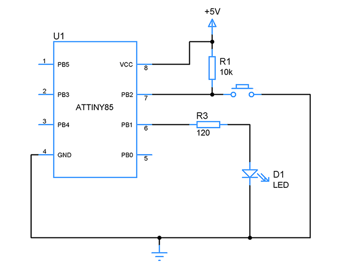


Would love a tutorial about brown out detect too. Thanks in advance!
Sure John, will publish an article about Brown out detector soon.
best and clean explanation. i came here for information about attiny85 watchdog timer and sleep modes. i understand sleepmode but can’t find information about watchdog. thake you very much for information provided
Thanks for the feedback Rajveer. We will publish a tutorial for Watchdog soon