Counters are essential peripheral in microcontrollers since it is used to count external events or internal / external clock pulses. Counters store the number of such events / pulses in registers for retrieval and processing. In ATtiny85 microcontroller, the counter can count up to 256 since its timer module is of 8 bit in size. Counters are generally used in the applications like frequency counters, digital clocks etc.
In this tutorial, we will be configuring the Attiny85 microcontroller as a counter that counts external event triggered by a push button. The counter basically uses the in built Timer peripheral to perform this function. The primary function of timers is to generate time delays. We are going to use Timer0 peripheral for demonstration purpose in this tutorial.
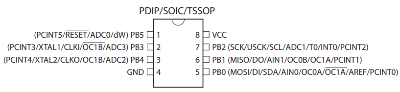
The counter can be configured to count internal or the external clock pulses. It’s very common to use external clock pulse than internal when comes to counter. In order for Timer/ Counter module to count external events / clock, it should be fed to PB0 pin which has alternative function of T0. The counter can be configured to count either on the positive edge or the negative edge of the clock cycle.
If you are intended to count the clock pulses of the external clock source then the frequency of the clock source must be less than half the system clock frequency (fExtClk < fclk_I/O / 2). Although it is recommended to limit the maximum frequency of external clock source to fclk_I/O / 2.5. Also remember the external clock source cannot be prescaled.
There are two timer/counter peripherals in ATtiny85 Timer0/counter 0 and Timer1/counter 1. In this tutorial we are going to use Timer0 and configure it as counter of external events. It is a 8 bit register which means it can count from 0 to 255.
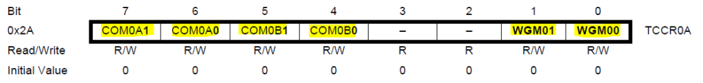
TCCR0A Register
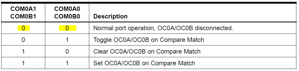
The following bits in TCCR0A register COM0A0, COM0A1, COM0B0, COM0B1 have to be cleared, to operate in the normal port operation. This disables the compare matching feature built within timer.
The bits WGM00, WGM01 from TCCR0A and WGM02 from TCCR0B determines mode of operation. Here the operation mode should be in Normal Mode. In this mode, the counting direction is always up that is it increments with each incoming pulse. The timer / counter overflows when the maximum value of 255 is reached. This overflow is marked by raising a oveflow flag which helps to trigger interrupt.
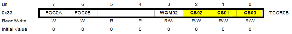
TCCR0B – Clock Source Configuring Register
Attiny85 consists of the 8-bit programmable bi-directional counter. As we are going to use external clock source for counting, we need to configure the bits CS0[2:0] in this register.
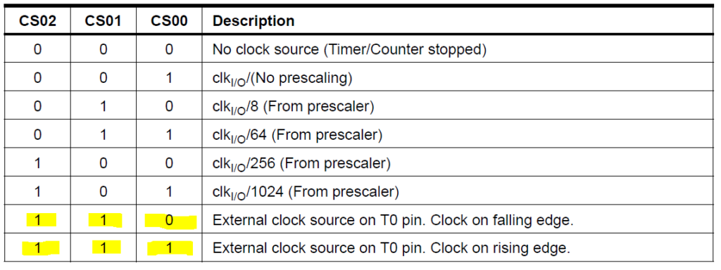
In TCCR0B control register the bits CS00, CS01 and CS02 clock select bits have to be configured.
The clock bits have to be set with either 1,1,0 or 1,1,1 respectively, to select the external clock source on T0 with a clock on falling or rising edge accordingly.
TIFR Flag Register
The TOV0 flag bit will be cleared automatically by hardware when interrupt is executed. Alternatively it can cleared manually by writing 1 to it.
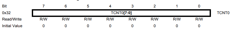
TCNT0 Register
This register stores the count value and the value in this register will be automatically incremented when new clock pulses or event input goes to T0 or PB0 pin.
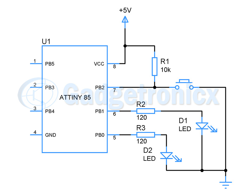
Circuit to count external events triggered by Push button:
This is the circuit setup we are using for this tutorial where a push button is used to simulate external events to PB2 or T0 pin. LED1 in PB1 and LED2 in PB0 added to to indicate when external event exceeds a particular limit.
Steps to configure Counter and derive the counts:
Select the normal mode of operation for timer/ counter 0
Select the external clock source on T0 with clock on Falling edge or rising edge
Read the TCNT0 register to obtain the number of external count.
Based on the count value in TCNT0 register we toggle LED1 or LED2.
Check for overflow flag TOV0 repeatedly to check if count exceeds 255.
Clear the overflow flag manually or use interrupt
Keep account for the number of overflows occurred along with the TCNT0 register value to obtain the real event count.
Sample counter code:
The below code was written to count external events triggered by push button to PB0 or T0 pin. When the event count exceeds 10 and stays within 30 LED lights up at PB1 and when event count exceeds 30 LED lights up at PB2.
#include<avr/io.h>
#define F_CPU 16500000UL
int i=0;

void counter_setup()
{
  DDRB=(1<<PB1)|(1<<PB0);
  TCCR0A = 0X00;               //TCCR0A to low for normal port operation and mode 0.
  TCCR0B = 0X00;                //WGM02=0
  TCCR0B |= (1<<CS02)|(1<<CS01);    //CS02=1, CS01=1 CS00=0 Clock on falling edge
  TCNT0 = 0x00;       //initializing the counter to 0
}

void  counter_reset()
{
  TCNT0=0x00;       //reset value to 0
  i=0;
}

int main()
{
 counter_setup();
 while(1)
 {
  i=TCNT0;
  if ( i>=10&&i<30)           // First 10 counts
   {
      PORTB |= (1 << PB1);   //light up LED in PB1
                     //reset counts
   }
  else if(i>=30)       //second 20 count
  {
    PORTB|=(1 << PB0);    //light up LED in PB2
    counter_reset();
  }
 }
}
Counting more than 255:
We can use interrupts or manual flag check method if you are looking to count more number of events or count incoming signal pulses. Using interrupts will be most effective as handling interrupts will be much more easier than manually checking overflow flag. In this case you can follow the interrupt part of ATtiny85 timer tutorial. It only differs with the choice of clock source selection. Below is the sample code that uses interrupt to keep count of events and it lights up LED in PB1 when the count crosses 1000.
#include<avr/io.h>
#define F_CPU 16500000UL
int i,j;
i=j=0;

void counter_setup()
{
 DDRB=(1<<PB1)|(1<<PB0);
 TCCR0A = 0X00; //TCCR0A to low for normal port operation and mode 0.
 TCCR0B = 0X00; //WGM02=0
 TCCR0B |= (1<<CS02)|(1<<CS01); //CS02=1, CS01=1 CS00=0 Clock on falling edge
 TCNT0 = 0x00; //initializing the counter to 0
 sei(); //enabling global interrupt
 TIMSK|=(1<<TOIE0); //enabling timer0 interrupt
}

ISR (TIMER0_OVF_vect)      //Interrupt vector for Timer0/Counter0
{
 i++;
}

int main()
{
 counter_setup();
 int actual_count;
 while(1)
  {
   j=TCNT0;
   actual_count=j+(i*256);
   if ( actual_count>=1000) // First 10 counts
    {
     PORTB |= (1 << PB1); //light up LED in PB1 if count reaches 1000
    }
  }
}
Try this out:
Configure ATtiny85 Timer0 and Timer1 to count and keep track of two external events. Set the maximum limit of event count to 1000.
Thank you for sharing your excellent YouTube video tutorials on the ATtiny85. I really like how you explain the details of the register bits and functions.
A couple of questions about the event counter tutorial:
1. Is the internal pullup on PB2 not available when Timer0 is set to use T0 as the input clock/count source? If it is, then why add the external 10K pullup for the push-button instead of configuring the pin as input with internal pullup?
2. Can Timer0 continue to count external events while the processor is in sleep mode? If not, can Timer1 operate in sleep mode, and does Timer1 have an external count input?
To explain question 2, I want to develop a battery-operated project that will count external events while the processor is in sleep mode (waking up the processor only if the timer/counter overflows, or when another event occurs to actually process the count value). So I am wondering if the ATtiny85 can simply count external events without waking up the processor (in order to save battery power). My intent is to use the other Timer 1 (or, perhaps, the watchdog timer), to periodically wake up the processor every “N” seconds, in order to process and save the result of the event counter from Timer 0. (If all this is possible. If not, I will probably try using a different processor that would have my required capabilities, such as a PIC12LF series, or a different 8 or 6 pin ATtiny device.)
Also a general comment/suggestion for your excellent tutorials.
As a person who is hard-of-hearing, I rely on YouTube’s closed captioning features, if available in the video (including the “auto-generated” captions if the YouTuber does not explicitly write their own captions). The YouTube captions are always displayed at the bottom of the video, in a black background, and YouTube does not offer a setting to reposition them elsewhere in the video (such as at the top instead of at the bottom).
Unfortunately, many YouTube providers do not think of audience members who require the captioning, and will often display important information (important or relevant ATtiny85 spec sheet details, for example 😉 or add their own text at the bottom of the video, so the information appears “underneath” and, therefore, hidden by the YouTube captions. When this happens, I have to pause the video, turn off captioning to see or read the hidden information or details, re-enable the captions and restart the video.
Could you please consider creating or editing your videos in such a way as to ensure important visual information always appear well above the YouTube closed captioning area? I and many other hard-of-hearing folks will be grateful if you can do that.

 TCCR0B – Clock Source Configuring Register
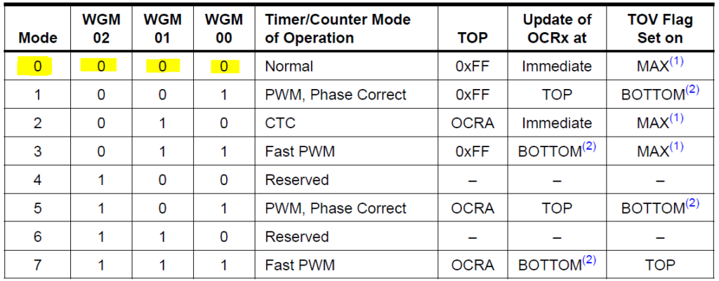
 The clock bits have to be set with either 1,1,0 or 1,1,1 respectively, to select the external clock source on T0 with a clock on falling or rising edge accordingly.
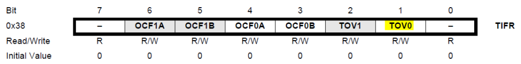


Sir,Can you please simplify circuit using attiny85 and Bluetooth module HC 05 or JDy 10 for smartphone Control toy car.
Hello, Frank.
Thank you for sharing your excellent YouTube video tutorials on the ATtiny85. I really like how you explain the details of the register bits and functions.
A couple of questions about the event counter tutorial:
1. Is the internal pullup on PB2 not available when Timer0 is set to use T0 as the input clock/count source? If it is, then why add the external 10K pullup for the push-button instead of configuring the pin as input with internal pullup?
2. Can Timer0 continue to count external events while the processor is in sleep mode? If not, can Timer1 operate in sleep mode, and does Timer1 have an external count input?
To explain question 2, I want to develop a battery-operated project that will count external events while the processor is in sleep mode (waking up the processor only if the timer/counter overflows, or when another event occurs to actually process the count value). So I am wondering if the ATtiny85 can simply count external events without waking up the processor (in order to save battery power). My intent is to use the other Timer 1 (or, perhaps, the watchdog timer), to periodically wake up the processor every “N” seconds, in order to process and save the result of the event counter from Timer 0. (If all this is possible. If not, I will probably try using a different processor that would have my required capabilities, such as a PIC12LF series, or a different 8 or 6 pin ATtiny device.)
Also a general comment/suggestion for your excellent tutorials.
As a person who is hard-of-hearing, I rely on YouTube’s closed captioning features, if available in the video (including the “auto-generated” captions if the YouTuber does not explicitly write their own captions). The YouTube captions are always displayed at the bottom of the video, in a black background, and YouTube does not offer a setting to reposition them elsewhere in the video (such as at the top instead of at the bottom).
Unfortunately, many YouTube providers do not think of audience members who require the captioning, and will often display important information (important or relevant ATtiny85 spec sheet details, for example 😉 or add their own text at the bottom of the video, so the information appears “underneath” and, therefore, hidden by the YouTube captions. When this happens, I have to pause the video, turn off captioning to see or read the hidden information or details, re-enable the captions and restart the video.
Could you please consider creating or editing your videos in such a way as to ensure important visual information always appear well above the YouTube closed captioning area? I and many other hard-of-hearing folks will be grateful if you can do that.