STM32 is the most popular 32-bit microcontroller among engineers and hobbyists. In this tutorial series we use STM32F103C8T6 microcontroller which belongs to this microcontroller family and will explain about the registers involved in using peripherals such as GPIO, USART, SPI, I2C and so on. Adding to that we will see how to program this microcontroller based development board using Arduino IDE and its libraries.
STM32F103C8T6:
STM32F103C8T6 is a 32-bit microcontroller with ARM CORTEX M3 architecture. It has 48 pins and 64KB flash memory. Below are some of the highlights of this microcontroller
Before heading onto programming this development board using Arduino IDE let’s dive inside this STM32 microcontrolller. If you are aware of how Microcontroller actually work you must have heard of registers. Every microcontroller has registers which needs to accessed to make the peripherals in it work as you intend. Though we are going to use Arduino IDE and program this one easily, it’s essential to understand about the registers involved.
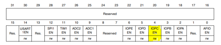
In this tutorial, GPIO pin ( PC13) is used activate and deactivate a LED. So we are going to review the registers associated with this GPIO pin PC13. In STM32 microcontroller to activate a particular port you need to access APB2 register. The APB2 register in this Microcontroller is shown below.
Out of that bit 16 to 31 are reserved, where user will not have any control. Bit 0 to 16 pins can be read or written. If you notice the bit 4 in the above register named IOPCEN controls the port C. GPIO Port C clock can be enabled by writing 1 to the bit IOPCEN. This activates the Port C and therefore any pin in Port C is now available for use to the user.
GPIOC_CRH REGISTER:
For the purpose of our tutorial we need to configure PC13 as output to light up the LED ON and OFF. Now we should choose the mode of operation of pin PC13 using register GPIOC_CRH. This register is responsible for configuring pins 8 to 15 in Port C. GPIOC_CRL is responsible for configuring pin 0 to 7 in Port C. Each pin has 4 bits dedicated to it which programmers can use to set the mode of operation. The below table explains various modes we can choose from.
If you observe the above table you can deduce register CNF1, CNF0 have to be written as ‘0’ to operate GPIO in Push-Pull mode. The MODE[1:0] bits should be configured to “0” & “1” which sets the maximum output speed to 10Mhz which is quite enough for our LED blink purpose. Now that the GPIO pin is configured as push pull output it’s all set to be turn ON and OFF the LED connected to it.
GPIOC_ODR REGISTER:
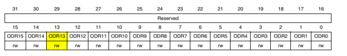
This is the output data register that controls the output of pins in PORTC. All the bits in this register is Read/ Write bit. In order to activate a particular pin all we have to do is write 1 to corresponding bit in this register. In our case we need to activate and deactivate Pin PC13 for which we need to write logic “1” to ODR13 bit and logic “0” to it.
So that’s how you activate a output pin in STM32F103C8T6 microcontroller. The registers associated and its usage is quite similar to other STM32 series microcontroller. That’s all the register we need to know for using GPIO pins of this microcontroller as output.
STM32 DEVELOPMENT BOARD:
STM32 development board popularly known as blue pill development board comes with STM32F103C8T6 microcontroller. It has two crystal oscillators of 8MHz and 32MHz which is used to drive the internal Real-Time Clock (RTC). The board can be operated with 3.3V supply but it has a voltage regulator IC to regulate the 5V supply to the board. The board can be used operate with low power mode in sleep mode. All the GPIO pins on the board can operate on 3.3V and are tolerant to 5V. The board contains an onboard LED which is internally connected to GPIO PC13.
PROGRAMMING STM32 BOARD:
Hope you have learnt about what goes in the background of programming a STM32 Microcontroller. Though we are programming using Arduino IDE using STM32 libraries, I believe it’s important for everyone of us to understand what goes in the background. Let’s get into programming STM32 board using Arduino IDE. Using this IDE you can code, debug the errors and upload it to MCU as well. In order to upload the code to STM32 we need a FTDI board which is a USB to serial converter. This board is extensively available online and you can get one quite easily.
To make the Arduino IDE ready to work with STM32 boards we need to install the board files in our Arduino IDE from boards manager. Use this STM32 package file link to install the library.
Now download the STM board library from board manager.
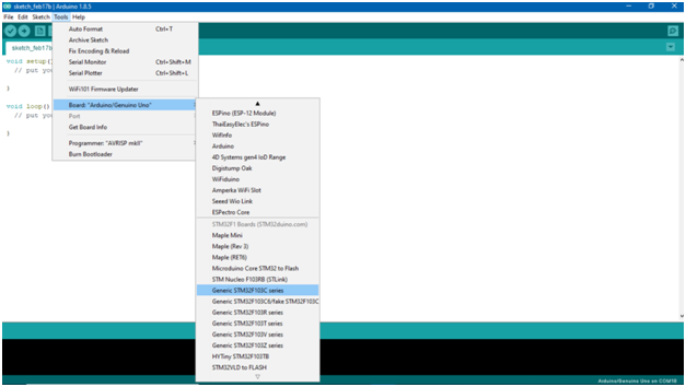
Finally, select the STM32F103C series from “Tools” to upload code to STM32 board.
Now the IDE setup is ready and the code can be dumped by using any of the below methods.
USING FTDI:
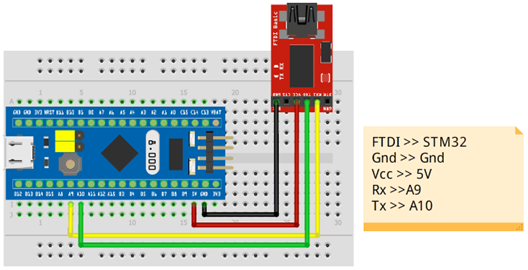
FTDI is a USB to Serial converter for translating the USB signals to serial communication signal so that our board can understand. The connections are shown in the below connection diagram. Remember the board has to be switched to programming mode by changing the boot0 jumper to 3.3V.
The IDE has to be set up in the following way to dump the code using FTDI.
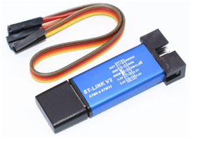
USING STLINK:
STLINK is an in-circuit debugger and programmer to dump the code into STM microcontrollers. This is a USB device and has to be directly connected to PC for code dumping.
Now the IDE options has to be changed to dump the code using STLINK
There is no need of boot jumper modification when the code is uploaded using STLINK. These two methods are widely in use for programming STM32 Blue pill board using Arduino IDE. Below are few other methods to program this board.
OTHER METHODS:
STM32 Cube programmer
Programming using bootloader
Keil
Atollic
BLINKING CODE:
Now that you are aware of programming methods of STM32 board. Let’s take the first step into coding with good old Blinker.
The LED is internally connected to Pin 13 of STM32 controller and we are activating and deactivating the LED with 1 sec delay between them.
This tutorial is very first of the STM32 tutorial series that will be published in our website in upcoming weeks. This tutorial is written by Nobel Chowdary, an upcoming Electronics engineer. Subscribe to our newsletter and Follow us through Social media for updates.

 Out of that bit 16 to 31 are reserved, where user will not have any control. Bit 0 to 16 pins can be read or written. If you notice the bit 4 in the above register named IOPCEN controls the port C. GPIO Port C clock can be enabled by writing 1 to the bit IOPCEN. This activates the Port C and therefore any pin in Port C is now available for use to the user.
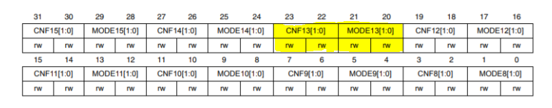 For the purpose of our tutorial we need to configure PC13 as output to light up the LED ON and OFF. Now we should choose the mode of operation of pin PC13 using register GPIOC_CRH. This register is responsible for configuring pins 8 to 15 in Port C. GPIOC_CRL is responsible for configuring pin 0 to 7 in Port C. Each pin has 4 bits dedicated to it which programmers can use to set the mode of operation. The below table explains various modes we can choose from.
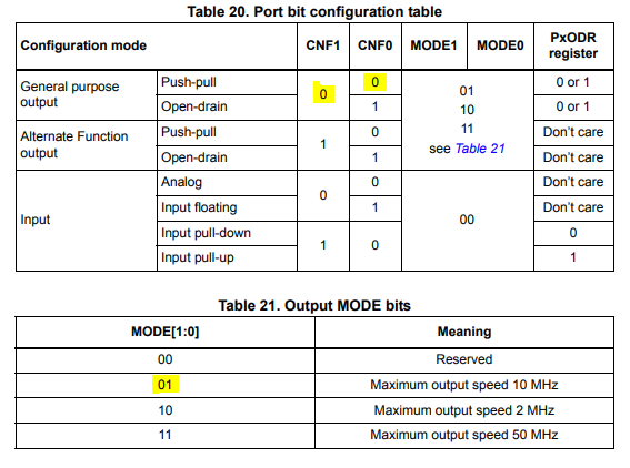
 This is the output data register that controls the output of pins in PORTC. All the bits in this register is Read/ Write bit. In order to activate a particular pin all we have to do is write 1 to corresponding bit in this register. In our case we need to activate and deactivate Pin PC13 for which we need to write logic “1” to ODR13 bit and logic “0” to it.
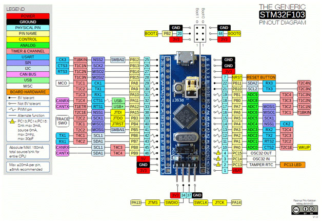 STM32 development board popularly known as blue pill development board comes with STM32F103C8T6 microcontroller. It has two crystal oscillators of 8MHz and 32MHz which is used to drive the internal Real-Time Clock (RTC). The board can be operated with 3.3V supply but it has a voltage regulator IC to regulate the 5V supply to the board. The board can be used operate with low power mode in sleep mode. All the GPIO pins on the board can operate on 3.3V and are tolerant to 5V. The board contains an onboard LED which is internally connected to GPIO PC13.
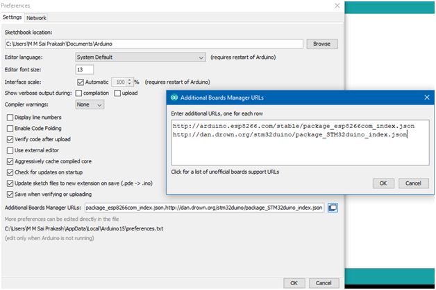 Now download the STM board library from board manager.
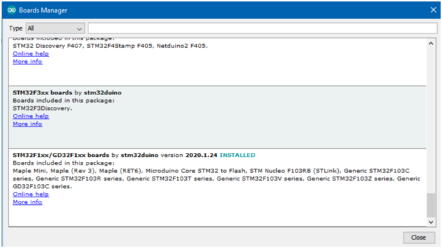
 The IDE has to be set up in the following way to dump the code using FTDI.
 USING STLINK:
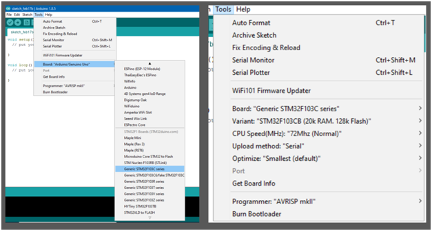
 Now the IDE options has to be changed to dump the code using STLINK
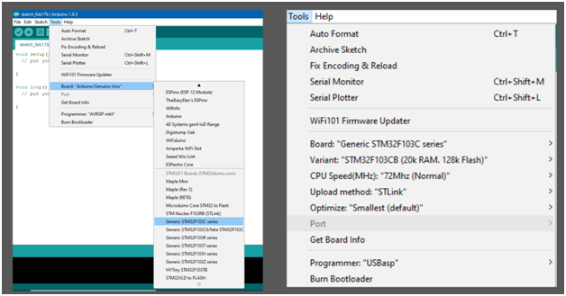


 Programming")


 Microcontroller")