Equalization is a technique that is widely used in studios for sound productions and recording. Using Audio Equalizer we can control different frequency bands from an audio spectrum using linear filters. Simply put using equalizer you can adjust which frequency ranges to allow and which range to reject from the audio signal. This will modify the pace, tone and other different aspects in an audio signal.
Most commonly used equalizers have 3 knobs to control the frequency ranges within bands such as bass, mid-range and treble. But some high end Equalizers have dedicated controls for each particular bands of frequencies to get more precise control. This Equalizer comes with three knobs where you can modify the audio signal as per your preference.
WORKING OF AUDIO EQUALIZER CIRCUIT :
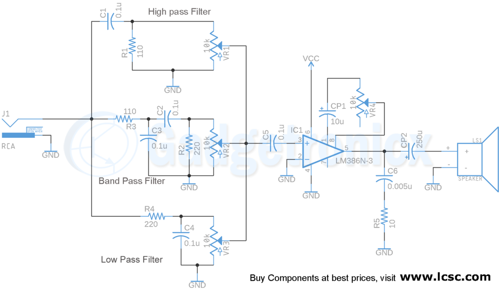
Making an audio Equalizer at home is very simple. We just need an audio amplifier and a couple of passive components to make a decent equalizer with good sound quality. This Equalizer circuit is comprised of four sections high pass filter, band pass filter, low pass filter for filtering the signal frequencies and an audio amplifier to boost the output audio signal’s strength.
SIGNAL FILTERS:
In the first stage of the circuit incoming signal is fed into our circuit using RCA connector. The signal is then fed through a series of filters High pass, Band pass and Low pass for filtering process. This filters are used to cut off the respective frequency of the source signal in the admissible ranges. For example the high pass filter will only allow to pass the frequency which are higher than the set frequency(fc). This fc is determined by the formula given below.
Let’s see how we choose the component values. As we know that the audible frequency range is from 20 Hz to 20Khz. So in order to get 3 distinct EQ – bands we need to split this range into 3 different bands. This gives us the approximate frequency value of 6.6kHz. Let’s take 7kHz for convenience. Now we need to fix center frequency for all these three filters.
LOW PASS FILTER:
The center frequency of a low pass filter is 7kHz which means the filter should block signals above this frequency. Using this center frequency we need to find out the value of R & C. First off let’s choose the value of the capacitor. Here we use a 0.1uf capacitor. So we just have to calculate the value of R.
So we put those values in the equation to determine the value of Resistor R.
fc = 1 / ( 2 * pi * R * C )
= 1 / ( 2 * 3.14 * R * 0.1uF )
R = 1 / ( 4.396 * 10-3 )
R = 220 ( We chose the closest standard value resistor )
HIGH PASS FILTER:
Let’s calculate the value of fc for high pass filter. The center frequency of high pass filter is fixed as 14Khz which means signal with frequency more than 14Khz will pass through this filter. Now to calculate the Resistor used in High pass filter fixing the value of Capacitor C as 0.1uF and applying in the formula gives
fc= 1 / ( 2 * pi * R * 0.1uF )
14Khz = 1 / ( 2 * 3.14 * R * 0.1uF )
R = 110 ( Choosing nearest standard value )
BAND PASS FILTER:
Now all that is left is band pass filter. This is quite tricky. So in order to get the filter set up for mid frequencies between 7khz to 14khz we use a band pass filter. This band pass filter is built using a low pass filter in series with a high pass filter. Keep in mind that center frequency of low pass filter used here should be greater than the high pass filter which is in series with it. And we wanted to cover the frequency range between 7.4kHz to 14.4kHz. To do this we should set the low pass filter center frequency to 14.4kHz and the high pass filter to 7.4kHz. Notice the resistor values are swapped for Low pass and High pass part of band pass filters.
Finally, we connect a potentiometer VR1, VR2 & VR3 parallel to each filter. This potentiometer will allow us to adjust the gain for each signals individually in way we prefer. The resultant sum of these signals will go to Audio amplifier to get amplified for output stage.
LM386 AUDIO AMPLIFIER:
We are using LM 386 audio amplifier IC in this audio amplifier. It’s cheap and easily available. It is used in low power audio power amplification applications. It’s internal gain is set to 20 but that can be adjusted using a capacitor in between the gain pins (pin 8 & pin 1). A variable resistor can also be used along with the capacitor for fine tuning of the gain.
As you can see in the circuit diagram there’s a capacitor CP1 and a variable resistor VR4 in between pin 1 and pin 8. to adjust the gain of IC. The output signal from three filters will be added in the Op-Amp input. The gain of summed up signals will be amplified in the output of LM386. This will be fed into output speaker connected to LM386. Typically using the capacitor and Potentiometer VR4 and CP1 we can adjust the overall signal gain from 26dB to 46dB. To get better idea about this amplifier read Audio amplifier using LM386.
NOTE:
By building this circuit you can get only Mono audio signals. If you want a stereo output you just need to make another Equalizer similar to this one. You can then pass the left channel of stereo audio signal to one EQ and the right channel to another. In this way you will have separate control for both of these audio channels and get a great audio / music.
PART LIST:
Audio source (Audio or RCA Jack)
Battery from 5 to 12V
Capacitor 0.1uF ( 5 ) , 0.005uF ( 1 ),
Polarized Capacitor 10u ( 1 ), 250u ( 1 )
IC LM386 Op-Amp
Speaker ( 8 to 32 Ohm )
Resistor 110 Ohm ( 2 ), 220 Ohm ( 2 ), 10 Ohm
Potentiometer 10k ( 4 )
Hope this Project was useful to you. If you have got any queries, feedback post them in the comment box below. Happy DIY 🙂


Why is there a capacitor (C5) before the input + into the LM386?