
Audio amplifiers are commonly used to amplify low power audio signals such as the signal from a radio receiver or microphone so that it can be used to drive loudspeakers or headphones. Commercially available amplifiers can be very expensive. So in this circuit we are about to see a Low cost audio amplifier an IC and few passive components. This circuit capable of amplifying audio signal that goes into a Microphone. We can use this circuit as a mini and portable loudspeaker system.
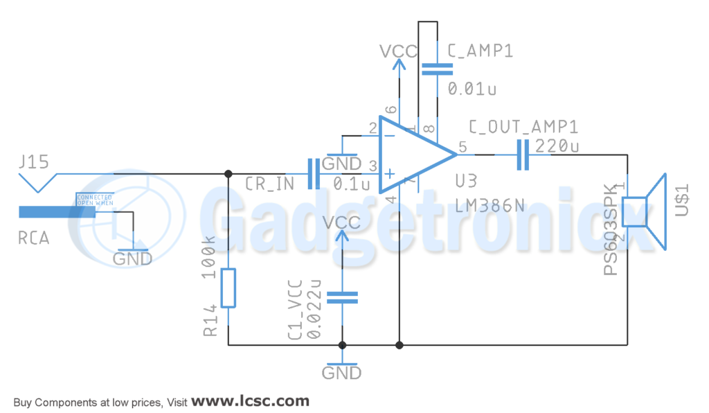
CIRCUIT DIAGRAM OF LOW COST AUDIO AMPLIFIER:
LM386 IC:
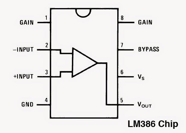
The IC we are going to use in this project is LM386 which is a low power audio frequency amplifier. It is suitable for low power applications since it draws very low quiescent current drain of only 4mA. It will last long even on battery power. The gain of the IC is internally set to 20 but by using a Capacitor we can increase it to any value from 20 to 200. Read more about Working of LM386 IC.
WORKING OF CIRCUIT:
Pin 1 and 8 are the gain control Pins. By using a capacitor between Pin 1 and 8 we can set the gain of this IC. Here we use 0.01uf capacitor in this circuit. Gain can be adjusted by varying different capacitor values. Pin 2 and 3 are the signal input pins. Pin 2 is the negative input terminal so this will be connected to the ground. 3rd pin is the positive input terminal. This will be connected to the signal audio source along with a RC filter circuitry. The capacitor CR_IN will help us to remove the DC component of input signal and only allow audio signal (AC component) to be fed into LM386 as a result input signal will be stabilized.
Pin 4 and 6 are the power supply Pins. Pin 6 for is Vcc and Pin 4 is Ground. Also we connect a capacitor to VCC for decoupling the power supply for the IC. We get the Amplified output signal from Pin 5. To reduce noise in the output side we will use another capacitor of 220uf for coupling the signal to speaker.
POWER SUPPLY :
The output power will depend on supply voltage and impedence or Ohm rating of a speaker. Here we used a 9V battery for the power supply, but the circuit can be powered with any voltage between 5 – 12v.
IMPROVING AUDIO QUALITY:
Note that by keeping all wire connections and components as close to the chip as possible will give less noisy output. Also try to keep the input ground separate from other ground paths as much as possible. This will help you get much better audio quality at the output. We can build two of this circuit so we can have stereo output,. We just need to pass each signal (Left and Right channel) for each amplifier followed goes to different speakers. Also if we connect some filters between them we can have our own stereo equalizer.
PARTLIST:
- Battery 12VDC
- Capacitor 0.022uF (1), Capacitor 0.1uF (2), 220uF (1)
- Resistor 100kOhm – 1
- OpAmp LM386N – 1
Hope this Circuit was useful to you. Do leave your queries and comments in the below section. Also do send us your Circuit design requests to webmaster(at)gadgetronicx.com .


So helpful, I follow every circuit that you post, as results I become much better in understanding secret behind electronic.
Thank you Bernard for your kind words 🙂