
RF projects are always special and I am confident that almost every engineer or enthusiast want to try building a RF project. Because of this we have put together a guide for building a super cool Walkie Talkie project. Walkie Talkie is a half duplex wireless communication device that is capable of establishing communication within short range. Half Duplex means only one user can speak or send his message at a time and communication cannot happen simultaneously. These devices are widely used by Security Personal, Industrial workers and so on. Of course it can make a great toy as well. This guide explains about a Walkie Talkie circuit that allows user to establish communication with another identical device within a range of 30m.
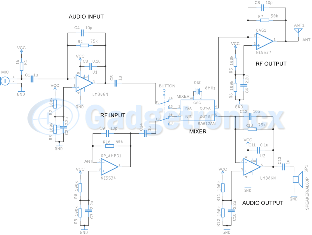
WALKIE TALKIE CIRCUIT DIAGRAM:
WORKING EXPLANATION:
The above Walkie Talkie circuit design can be divided into five different parts. The Audio input , Audio output, RF input , RF output and Mixer. For the purpose of easier understanding am going explain the working of above parts of this circuit individually and then put it together as one piece.
TRANSMITTER SECTION:
AUDIO INPUT:
This is the first section of this project. This section of the circuit takes audio input from the user. The Microphone MIC translate the sound from user to electrical signals. The audio input signal from Microphone is too weak to use therefore we have used an audio amplifier using Op amp LM386. If you have known LM386 this chip is dedicated for amplifying Audio signals. The amplified output from LM386 goes through coupling capacitor C5. This will eliminate DC elements from the amplified signal and only allows AC components in the signal. The signal then goes to a Push Button ( DPDT type ). We will come to this button shortly.
MIXER:
The amplified signal from LM386 Audio amplifier goes to Mixer IC SA612AN that is connected to 8Mhz crystal Oscillator. The purpose of mixer here is that it modulates the amplified audio signal with respect o 8Mhz carrier signal so it can travel as higher frequency signal through the air. Without modulation wireless transmission cannot occur.
RF OUTPUT:
Now the modulated signal goes to the RF output section. And before radiating the signal via antenna it goes to a RF amplifier built around IC NE5537. This OpAmp NE5537 has a higher bandwidth frequency response making it suitable to amplify for signal to be transmitted as RF signal.
The above three sections of the circuit forms the transmitter part of our Walkie talkie project. Here voice signal from user is being amplified by Audio amplifier, modulated by Mixer and then amplified by RF amplifier and transmitted to environment via Antenna.
RECEIVER SECTION:
To receive a signal this Walkie Talkie project uses same Antenna ANT1 which is used to transmit the voice signals as we saw in the previous section. The received audio signal from the Antenna goes to RF input section of the circuit.
RF INPUT:
Once the transmitted signal is in it goes through an NE5534 based amplifier to boost the signal. Any signal subjected to transmission looses its strength and must be amplified in the receiver end and that’s that purpose of this NE5534 amplifier. Once the signal is boosted up it goes to the same mixer where the audio input from transmitter section goes for modulation. Only difference is that now the signal goes for demodulation to the mixer.
MIXER:
Signal from the RF input section is meant for demodulation. The purpose of demodulation here is to return the signal to original audio frequency so user can listen and understand the message. But the Mixer IC SA612AN doesn’t meant for demodulating signals, it can only mix the incoming signal with 8Mhz Carrier signal generated using crystal oscillator. So you might ask how does the demodulation occurs to obtain the original audio or speech signal ? Simple all mixer does is always mixing the input signal with a 8Mhz signal when you mix a low frequency signal with a high frequency you have the signal modulated at higher frequency but when you mix two signals with similar frequencies the signals will be split.
RF OUTPUT:
The signal from the mixer contains low frequency Audio signal and high frequency carrier signal but with double of its frequency. This signal will further passed to an output stage amplifier built using LM386. As we all knew Audio amplifier will amplify only the signal that lies within the audio or speech frequency and discards higher frequency signals. This eliminates the high frequency carrier component in the signal. The audio signal on the other hand gets amplified and sent to speaker connected in the output of LM386. Thus we can listen to the message that sender is transmitting from other Walkie Talkie device.
This ends the receiver part of this Walkie Talkie project. The receiver section comprises of Antenna ( the same one used for transmitting voice signals ), RF input section to amplify incoming voice signal and Mixer to demodulate the signal and finally output stage amplifier to filter and amplify voice signal and then direct it to the speaker for listening to transmitted voice signal.
BUTTON:
So now it’s been established what makes the Transmitter and Receiver part of this Walkie Talkie project. As you have noticed the above circuit serves as both Transmitter and Receiver. And using Walkie Talkie you can either speak or listen at a time and not both. So this means that this circuit can either function as a Transmitter or Receiver at a time and not both. And that’s where this DPDT button comes into picture. The position of this switch decides whether the circuit is in Transmitter mode or Receiver mode. If you observe the position of this Button in the circuit it connects the output from RF input section goes to IN-B pin of Mixer and corresponding output goes to Audio output section and finally to the speaker delivering the message. In this state the Circuit functions as a Receiver of message from an identical Walkie Talkie device.
On another instant if the button is toggled, it connects the output from Audio input section to IN A pin of Mixer IC and delivers the modulated signal output via OUT A. This signal then goes to RF Output section and radiated into the atmosphere. In this state the circuit functions as a transmitter transmitting the audio input speech signal to its identical Walkie Talkie device. So I believe now you must have understood the importance of this button. This button determines the functioning of the above circuit either as a Transmitter or Receiver at a given time.
HOW TO USE THIS WALKIE TALKIE CIRCUIT:
- Build two circuits enabling two users to use, lets call them User 1 and User 2.
- By default this Walkie Talkie circuit will be in Receiver state.
- When User 1 wants to transmit a message to User 2, he should press the Button to enable transmitter state in his circuit and then speak.
- Upon finishing his message he should mention “Over” which means he finished transmitting his message.
- User 1 should release the Button to enable the device to return to receiver state.
- By this time User 2 would have got the message from User 1.
- It’s User 2 turn to press the button and enable transmitter mode in his circuit and reply to User 1 message
- The cycle continues.
COMPONENTS REQUIRED:
- 9V / 500mAh Battery
- RF Antenna
- 12 Ohm Speaker
- 1uF Capacitor – 4
- 2.2uF Capacitor – 4
- 10pF Capacitor – 4
- 0.1uF Capacitor – 2
- Mixer IC SA612AN
- Electret Microphone – 1
- Op Amp NE5534 – 2
- Op Amp LM386 – 2
- 1k Ohm Resistor – 2
- 100k Ohm Resistor – 8
- 75k Ohm Resistor – 2
- 50k Ohm Resistor – 2
- Crystal Oscillator 8MHz ABM3B – 1
NOTE:
- You need to build two of these circuits one for each user.
- Use Push button DPDT switch for the Button.
- Quality Electret Microphone should be used with this circuit.


Bro can you help me on this I am having trouble in finding the antenna type?