Model trains are fun toys which every one of us used to play with in our childhood. Many sophisticated and attractive model trains are available in the market now a days yet the basic principle in build a controller for it remains the same. I built a Model train controller which is equipped with Acceleration and deceleration control using the PWM technique. And also Forward reverse button to control the direction.
MODEL TRAIN CONTROLLER CIRCUIT:
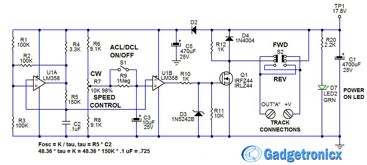
CONTROLLER UNIT:
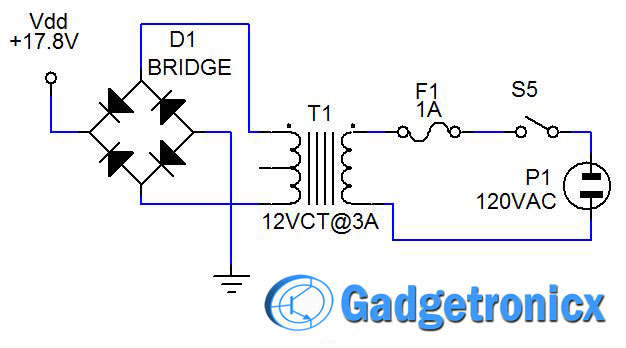
POWER SUPPLY UNIT:
WORKING OF CIRCUIT DIAGRAM:
Please refer to Controller unit circuit for this discussion. The heart of the oscillator is U1A, R1-R5, and C2. R1 and R3 divide the V1 supply voltage in half and their combined resistance is R1*R3/(R1+R3) = 50K. Since R2 = 100K, when the output of U1A switches from ground to 15 volts (+V1), the junction of U1A+, and R1, R2, R3, switches from 5 volts to 10 volts. R5 starts charging C2. When C2 charges above 10 volts, the input of U1A- is higher than U1A+. That causes the output of U1A to switch to 0 volts. In turn, the junction of U1A+, and R1, R2, R3, switches from 10 volts to 5 volts. R5 begins to discharge C2. When C2 discharges below 5 volts, the input of U1A- is lower than U1A+.
The output of U1A switches from 0 volts to 15 volts (+V1), the junction of U1A+, and R1, R2, R3, switches from 5 volts to 10 volts. R5 begins to charge C2 and the cycle keeps repeating. C2 is constantly ramping up and down between +V1*1/3 (5V) and +V1*2/3 (10V). The really cool thing is that this circuit oscillates at the same frequency even if the supply voltage +V1 changes! The oscillator frequency chosen for the train controller is about 50 Hz (20 mS period).
The low frequency was chosen so that the motor armature could turn slowly, one segment at a time for control at very slow speeds. Train motors generally have a 2 mS to 5 mS time constant and therefore the PWM period must be at least five to ten times as long in order to have good slow speed control.
SPEED CONTROL UNIT:
U1B acts as a comparator to provide the 0% to 100% PWM output. R6, R7, and R8 form a resistive divider. Notice that R6 and R8 are 10% lower resistance than potentiometer R7. Doing the math 15*(R7+R8)/(R6+R7+R8) = 15*19.1K/(28.2K) = 10.16 volts at full clockwise (100% ON), and 15*R8/(R6+R7+R8) = 15*9.1/28.2 = 4.84 volts at full counter-clockwise (0% OFF). The U1B- input is connected to the junction of R5 and C2 which ramps up and down between 5 and 10 volts. U1B+ is connected to the wiper on potentiometer R7.
Whenever the oscillator ramp voltage is lower than the wiper reference voltage, the output of U1B goes high and whenever the oscillator ramp voltage is higher than the wiper reference voltage, the output of U1B is low. Since the wiper reference voltage can be set lower than the lowest ramp voltage, 100% ON time is possible. Additionally, since the wiper reference voltage can be set higher than the highest ramp voltage, 0% ON time (100% OFF) is possible. This cannot be done with a 555 timer. So OFF can really be OFF and ON can be full ON.
The output of U1B is connected to a switch to power the load. In Figure 1, the output is connected via R10 to the gate of Q1, which is an IRLZ44 MOSFET transistor. D3 and R11 protect the gate of Q1 from being over-driven with voltage. R12 provides a light resistive load to Q1, while D4 protects Q1 from inductive load, voltage spikes.
S1, R9, and C3 provide the ACCEL/DECEL function for the train controller. When switch S1, Accel/Decel ON/OFF, is open, R9 and C3 cause the wiper reference voltage, at the input of U1B+, to change very slowly as R7 is adjusted up or down. This provides a slow acceleration or a momentum effect for a model railroad train. The ACCEL/DECAL time constant, set by R9 and C3, is around 30 seconds. That is the time needed to accelerate to full speed or decelerate to a stop. Switch S2, a DPDT slide switch, is wired to provide the Forward/Reverse polarity function.
The above circuit was designed for a two channel, track or train control. However you can expand this circuit to control up to 3 channels. In order to do that Duplicate R6-R12, C3, U1B, D3-D4 and Q1, use IC LM324 quad Op-amp for 2 or 3 channels. Channel 2 designations = U1C, R6=R13, R7=R14, R8=15, R9=R16, C3=C4, R10=R17, R11=R18, D3=D5, R13=R19, D4=D6,Q1=Q2,S1=S3,S2=S4. Doing this you will get extra channels in your project.
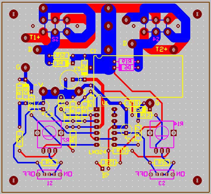
PCB DESIGN:
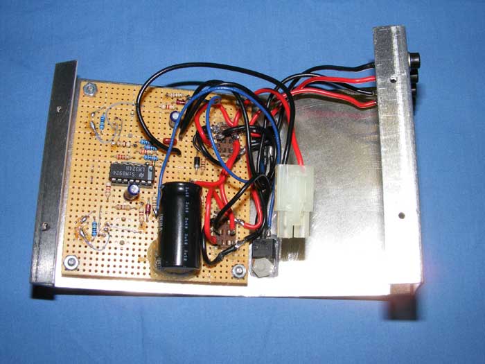
BUILT CONTROLLER:
Internal Circuit board of controller
Dual Channel Train controller
GERBER FILES:
You can download the Gerber files for this circuit below.
Bonjour Ron,
Est ce que cette alimentation en PWM est compatible pour l’echelle Z. La tension maximum ne doit pas dépasser 10 volts.
Merci d’avance
Christophe
Built this July 2021 on veroboard. I added a LED between positive rail and drain on MOSFET (with a 3.3K limiting resistor) that way you can actually ‘see’ the pulses. I just used a single (two channel) LM358. Only bothered because I had a spare case but works fine. On a fairly small layout the 1M resistor providing the momentum is too big, acceleration too slow so I changed it to 500K. What I find odd is that with the train stationary both rails are at positive rail voltage whereas with most controlllers they are at zero. That might confuse some add ons like auto stop modules.
Hi Frank, That is because the N-channel MOSFET is connected to ground. Therefore when it is OFF, the rails will both be high due to the conduction of the train’s motor. The only time one rail is high and the other is low is when the MOSFET is ON. It would be possible to reverse this by using a P-channel MOSFET on the positive side, but they a re more expensive and have higher Rdson resistance. I used the 1 meg resistor in the Accel/Decel circuit to provide for a 30 second Accel/Decel time. Lowering it to 500K cuts that in half to about 15 seconds and appears to work best for your layout. I encourage everyone to make modifications to fit their needs. Nice job!
Dear Ron
Would it be possible to send the Gerber files of the circuit for simple control, the one you disclose in the electrical diagram at the beginning of the article, using the LM 358 and the Mosfet IRFZ44?
The attached Gerber files are for double control and I’m sorry if I’m saying something stupid, I’m a layman in electronics and I want to improve the speed controller of my train, the original control of my set is limited and with no possibility of control at low speeds and due to the size and design of the layout is necessary.
I have already modified all line turnouts, automating and making keys more secure and accurate
My email is jackson.blecker@gmail.com and I appreciate any comments or ideas.
Thanks
Hi Jason, The Gerber files and circuit use an LM324 quad op-amp chip. One op-amp is used for the oscillator. The other three op-amps are available for use as a comparators to output a PWM signal to three IRFZ44 MOSFETS used to power the train track. The unit I built used only three of the op-amps, one as the oscillator and two as comparators to run two separate tracks. This allows for two separate trains to be run at the same time, or two separate blocks of track to be controlled independently. You can build it and simply don’t connect the second channel. Use just one IRFZ44 connected to the first comparator and leave the rest other op-amps unused. I think you should build it as a two channel unit to give you the option of running a second block of track or two separate loops for two trains. The cost for the extra channel is minimal. Good luck with your project. Let me know how it turns out.
HI Ron
I’m returning to my model controller project and I’ve already bought the components and I have a company that will make the PC boards.
Analyzing the gerber files I have a doubt, in file HEI_PWM_tm_ Crtl_A w-Acl-Dcl_4B.GTO there are points marked: T1+, T1-, T2+, T2-, V- and V+. I would like to know, if possible, what this encoding means and what are the INPUT points and the OUTPUT on the board.
If you have an email I can send the entire list of material purchased and pictures of the boards, I tried to give a balance since my layout is small.
Thank you very much for the help so far, the project is slow but now I hope to finish soon.


I made this awesome circuit and works really well, tgank you for posting,is there short circuit protection though?
Hi Found an Error, I think R19 should = R12 not R13?
Bonjour Ron,
Est ce que cette alimentation en PWM est compatible pour l’echelle Z. La tension maximum ne doit pas dépasser 10 volts.
Merci d’avance
Christophe
Built this July 2021 on veroboard. I added a LED between positive rail and drain on MOSFET (with a 3.3K limiting resistor) that way you can actually ‘see’ the pulses. I just used a single (two channel) LM358. Only bothered because I had a spare case but works fine. On a fairly small layout the 1M resistor providing the momentum is too big, acceleration too slow so I changed it to 500K. What I find odd is that with the train stationary both rails are at positive rail voltage whereas with most controlllers they are at zero. That might confuse some add ons like auto stop modules.
Hi Frank, That is because the N-channel MOSFET is connected to ground. Therefore when it is OFF, the rails will both be high due to the conduction of the train’s motor. The only time one rail is high and the other is low is when the MOSFET is ON. It would be possible to reverse this by using a P-channel MOSFET on the positive side, but they a re more expensive and have higher Rdson resistance. I used the 1 meg resistor in the Accel/Decel circuit to provide for a 30 second Accel/Decel time. Lowering it to 500K cuts that in half to about 15 seconds and appears to work best for your layout. I encourage everyone to make modifications to fit their needs. Nice job!
Dear Ron
Would it be possible to send the Gerber files of the circuit for simple control, the one you disclose in the electrical diagram at the beginning of the article, using the LM 358 and the Mosfet IRFZ44?
The attached Gerber files are for double control and I’m sorry if I’m saying something stupid, I’m a layman in electronics and I want to improve the speed controller of my train, the original control of my set is limited and with no possibility of control at low speeds and due to the size and design of the layout is necessary.
I have already modified all line turnouts, automating and making keys more secure and accurate
My email is jackson.blecker@gmail.com and I appreciate any comments or ideas.
Thanks
Hi Jason, The Gerber files and circuit use an LM324 quad op-amp chip. One op-amp is used for the oscillator. The other three op-amps are available for use as a comparators to output a PWM signal to three IRFZ44 MOSFETS used to power the train track. The unit I built used only three of the op-amps, one as the oscillator and two as comparators to run two separate tracks. This allows for two separate trains to be run at the same time, or two separate blocks of track to be controlled independently. You can build it and simply don’t connect the second channel. Use just one IRFZ44 connected to the first comparator and leave the rest other op-amps unused. I think you should build it as a two channel unit to give you the option of running a second block of track or two separate loops for two trains. The cost for the extra channel is minimal. Good luck with your project. Let me know how it turns out.
HI Ron
I’m returning to my model controller project and I’ve already bought the components and I have a company that will make the PC boards.
Analyzing the gerber files I have a doubt, in file HEI_PWM_tm_ Crtl_A w-Acl-Dcl_4B.GTO there are points marked: T1+, T1-, T2+, T2-, V- and V+. I would like to know, if possible, what this encoding means and what are the INPUT points and the OUTPUT on the board.
If you have an email I can send the entire list of material purchased and pictures of the boards, I tried to give a balance since my layout is small.
Thank you very much for the help so far, the project is slow but now I hope to finish soon.
Jackson