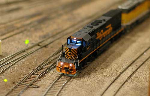
Model trains are fun toys which every one of us used to play with in our childhood. Many sophisticated and attractive model trains are available in the market now a days yet the basic principle in build a controller for it remains the same. I built a Model train controller which is equipped with Acceleration and deceleration control using the PWM technique. And also Forward reverse button to control the direction.
MODEL TRAIN CONTROLLER CIRCUIT:
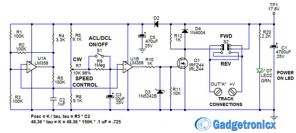
CONTROLLER UNIT:
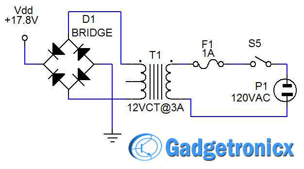
POWER SUPPLY UNIT:
WORKING OF CIRCUIT DIAGRAM:
Please refer to Controller unit circuit for this discussion. The heart of the oscillator is U1A, R1-R5, and C2. R1 and R3 divide the V1 supply voltage in half and their combined resistance is R1*R3/(R1+R3) = 50K. Since R2 = 100K, when the output of U1A switches from ground to 15 volts (+V1), the junction of U1A+, and R1, R2, R3, switches from 5 volts to 10 volts. R5 starts charging C2. When C2 charges above 10 volts, the input of U1A- is higher than U1A+. That causes the output of U1A to switch to 0 volts. In turn, the junction of U1A+, and R1, R2, R3, switches from 10 volts to 5 volts. R5 begins to discharge C2. When C2 discharges below 5 volts, the input of U1A- is lower than U1A+.
The output of U1A switches from 0 volts to 15 volts (+V1), the junction of U1A+, and R1, R2, R3, switches from 5 volts to 10 volts. R5 begins to charge C2 and the cycle keeps repeating. C2 is constantly ramping up and down between +V1*1/3 (5V) and +V1*2/3 (10V). The really cool thing is that this circuit oscillates at the same frequency even if the supply voltage +V1 changes! The oscillator frequency chosen for the train controller is about 50 Hz (20 mS period).
The low frequency was chosen so that the motor armature could turn slowly, one segment at a time for control at very slow speeds. Train motors generally have a 2 mS to 5 mS time constant and therefore the PWM period must be at least five to ten times as long in order to have good slow speed control.
SPEED CONTROL UNIT:
U1B acts as a comparator to provide the 0% to 100% PWM output. R6, R7, and R8 form a resistive divider. Notice that R6 and R8 are 10% lower resistance than potentiometer R7. Doing the math 15*(R7+R8)/(R6+R7+R8) = 15*19.1K/(28.2K) = 10.16 volts at full clockwise (100% ON), and 15*R8/(R6+R7+R8) = 15*9.1/28.2 = 4.84 volts at full counter-clockwise (0% OFF). The U1B- input is connected to the junction of R5 and C2 which ramps up and down between 5 and 10 volts. U1B+ is connected to the wiper on potentiometer R7.
Whenever the oscillator ramp voltage is lower than the wiper reference voltage, the output of U1B goes high and whenever the oscillator ramp voltage is higher than the wiper reference voltage, the output of U1B is low. Since the wiper reference voltage can be set lower than the lowest ramp voltage, 100% ON time is possible. Additionally, since the wiper reference voltage can be set higher than the highest ramp voltage, 0% ON time (100% OFF) is possible. This cannot be done with a 555 timer. So OFF can really be OFF and ON can be full ON.
The output of U1B is connected to a switch to power the load. In Figure 1, the output is connected via R10 to the gate of Q1, which is an IRLZ44 MOSFET transistor. D3 and R11 protect the gate of Q1 from being over-driven with voltage. R12 provides a light resistive load to Q1, while D4 protects Q1 from inductive load, voltage spikes.
S1, R9, and C3 provide the ACCEL/DECEL function for the train controller. When switch S1, Accel/Decel ON/OFF, is open, R9 and C3 cause the wiper reference voltage, at the input of U1B+, to change very slowly as R7 is adjusted up or down. This provides a slow acceleration or a momentum effect for a model railroad train. The ACCEL/DECAL time constant, set by R9 and C3, is around 30 seconds. That is the time needed to accelerate to full speed or decelerate to a stop. Switch S2, a DPDT slide switch, is wired to provide the Forward/Reverse polarity function.
The above circuit was designed for a two channel, track or train control. However you can expand this circuit to control up to 3 channels. In order to do that Duplicate R6-R12, C3, U1B, D3-D4 and Q1, use IC LM324 quad Op-amp for 2 or 3 channels. Channel 2 designations = U1C, R6=R13, R7=R14, R8=15, R9=R16, C3=C4, R10=R17, R11=R18, D3=D5, R13=R19, D4=D6,Q1=Q2,S1=S3,S2=S4. Doing this you will get extra channels in your project.
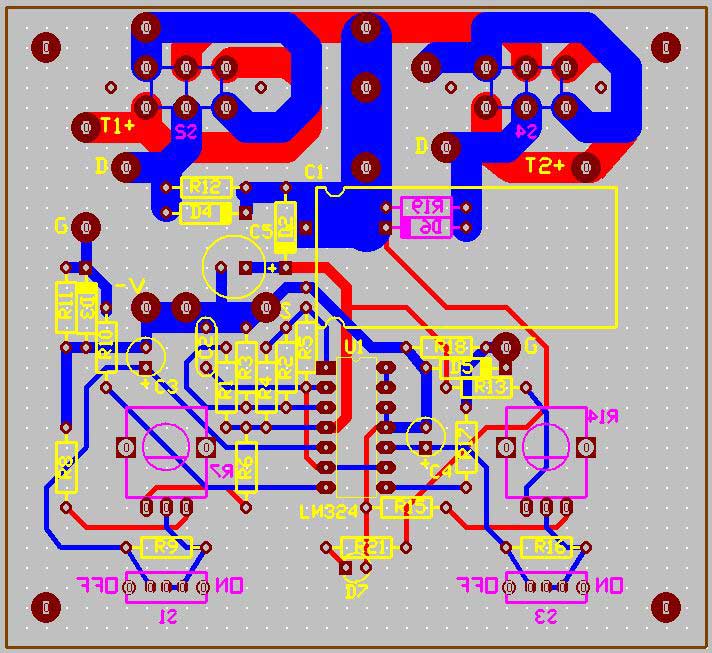
PCB DESIGN:
BUILT CONTROLLER:
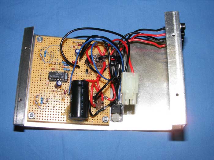
Internal Circuit board of controller
Dual Channel Train controller
GERBER FILES:
You can download the Gerber files for this circuit below.
Dear Ron:
Perform model train controler assembly and order PCB manufacturing and I’m having trouble getting it to work properly. The locomotive only starts when the potentiometer is about halfway through its path giving the locomotive at a fixed speed and I do not get the varying speed to back up the potrenciometer severing the engine.
I beg you to give me a clue to solve this problem
Ron, I am at the planning stage to set up my model railroad again. I bought this train set in 1982 and have no desire to convert to digital. Your description of your train controller is therefore of great interest to me. However my knowledge of electronics is very basic, so I would like to ask how this train controller works in operation. Referring to your picture: Dual Channel Train controller which knob would I use first to start a locomotive? With the SPEED dial would I pre-set the maximum speed but the train would get into motion only when ACCELERATION is switched on, likewise how does the DECELERATION work. My apologies for not being able to ask you are more technical question. I am looking forward to your remarks.
Hi – how does the circuit handle one PWM driver output feeding in to another ? I am thinking about the situation when a train goes from one segment being controlled by PWM driver #1 and the wheels cross over onto the tracks being controlled by PWM driver #2 ? This would effectively join the PWM outputs together and could cause shoot through / short to ground.
Since both MOSFETS are connected to ground, the only problem would be if the track polarities were reversed. As long as the direction for both track segments is the same, the train may change speeds at crossover, but there would be no shoot through. Shoot through could only occur if the track direction for the two tracks were opposite, and then only when the wheels shorted the two track segments.
Hi Ron – I like the design ! Would it be possible to grab the PCB Gerber files ? Also, do you get any low frequency PWM motor noise ? I have contemplated building a circuit that uses 20kHz PWM to remove the high pitch motor winding noise. Cheers !
Hi Brant. The Gerber files are available. The motor growls at very low speeds which actually sounds really cool. at 30% or more duty cycle, the motor noise is only like a motor on a DC supply. A 20 kHz PWM will act the same as a DC supply. The train will sit still and all of a sudden start moving. The 50 Hz rate, allows you to control the motor at very low speeds. Send me your e-mail address if you would like the Gerbers.
The IRFZ44 can withstand 60 A. The transformer only puts out 3 A, and the fuse would blow if a short circuit lasts too long. Current limiting of the IRFZ44 would actually cause it to heat up more than having it on hard during the short.
Hi To all
Current limiting in any model train controller is a bad thing. The current needs to cut off completely in the event of a short circuit or any other form of overload. This is known as Foldback current control. The current is folded back to zero on overload. You mention a fuse. What fuse? Not all transformers have inbuilt fuses. Your circuit although credit worthy needs a better idea than simply relying on transformer limiting. Sorry Ron but I have to say this technique is not good design.
Jeff
I have been using this circuit on my layout for 15 years and have never had a problem. Foldback limiting adds more complexity, expense, and can cause erratic behavior when operating on grades, or with long trains. This circuit works perfect and the short circuit condition has never been an issue. In the event of a derailment, the user simply turns down the throttle, then rerails the train and continues. Like I said, no problem.
Sorry for taking so long to reply. I have been overseas.
Never had a problem in 15 years with this overload configuration means you have been lucky. It does not mean the technique is good.
You say that adding foldback current control is more expensive and complex. You can’t be serious. less than $5 worth of parts are needed and is that not worth it given some locos can cost many hundreds of dollars?
I wish you well with this design but at least do your readers a favour and warn them of the possible problems with the design.
cheers – Jeff Monegal
Hi Martin, There are several ways to do this project. I built the unit I use and is in the article by using a .1″ proto-board and point to point wiring. The slide switches required cutting out a rectangular area for the switch lugs and wiring them with the eighteen gauge wire to the board and the output terminals. Use the double-sided, blue-red, picture to show you how to place the components and wire the unit. I can send you Gerber files if you would like. Then you could order PCB from ExPress Circuits, Easy PCB, Sunstone Circuits, or any of the many vendors on the internet. The only problem might be finding and connecting the large slide switches to the board. The circuit is pretty simple and point-to-point wiring might be the least costly and easiest method to build the unit. Best wishes for your successful build. Regards, Ron H.
you can send the gerber files to PCB 123 or Sunstone circuits and they will make you a circuit board. Send me your e-mail address and I will send the Gerber files to you.
I can’t remember if I uploaded the Gerber files to the Gadgetronicx website or not. I will e-mail them to you if you wish. Send them to PCBWay and request a quote.
Ron, I was wondering how much current the output stage can handle. I like to run more than one engine on a train and wondered if this would handle it. Also, I have several 5k one watt pots and was wondering if I could change the voltage divider of R6,R7 and R8 to accommodate a 5K pot.
Tom, The pot value is needed to provide full 0% to 100% control. Also, the larger value greatly reduces the current used by the divider reference circuit. You can change R6 and R8 to 4.7K or to 4.3K. I selected a value that was 10% less than the value of the control pot to ensure that the output could be set from full OFF (0%) to full ON (100%). Some pots have terrible tolerance +/- 20%, so measure them. The 4.3K resistor value would probably work best, but it would reduce the adjustment range. The output MOSFETS can handle 50 Amps. The limit is the power transformer. The one I used was rated 12 Volts at 3 Amps. If you use a larger transformer, you could run 10 Amps with no problem. Most HO scale trains use 1 amp or less depending on the length of the train, grade (slope) of the track, and type of engine (number of drivers). Let me know how your finished unit works. Best wishes, Ron H.
Keith, diode D2 provides isolation between the op-amp filter circuits, (capacitor C5), and the main power supply. This provides stable operation of the op-amps during heavy current use by the train or lamp loads. Diode D4, on the other hand, provides a shunt pathway for the inductive spikes created by motor or inductive loads. It limits the spike amplitude to about ,6 volts above the power supply positive rail. This protects the IRFZ44 from being damaged due to secondary, (or overvoltage), breakdown.
Ron, thank you for your response and for your explanation of the circuit’s operation. On a more basic note, I was wondering what the diode is. Is it a 1N4004? The schematic doesn’t list it.
Thank you again for sharing your work with us!
Keith


Dear Ron:
Perform model train controler assembly and order PCB manufacturing and I’m having trouble getting it to work properly. The locomotive only starts when the potentiometer is about halfway through its path giving the locomotive at a fixed speed and I do not get the varying speed to back up the potrenciometer severing the engine.
I beg you to give me a clue to solve this problem
hello Ron,
Your controller is great and could you please send me the pcb file and the gerber to my email psfilho@gmail.com.
Thank you very much
Hey Paulo,
The article is updated with Gerber files of this project. Check them out 🙂 Thanks to Ron
Ron, I am at the planning stage to set up my model railroad again. I bought this train set in 1982 and have no desire to convert to digital. Your description of your train controller is therefore of great interest to me. However my knowledge of electronics is very basic, so I would like to ask how this train controller works in operation. Referring to your picture: Dual Channel Train controller which knob would I use first to start a locomotive? With the SPEED dial would I pre-set the maximum speed but the train would get into motion only when ACCELERATION is switched on, likewise how does the DECELERATION work. My apologies for not being able to ask you are more technical question. I am looking forward to your remarks.
I sent you answers via e-mail. Let me know how the finished controller turns out.
Hi – how does the circuit handle one PWM driver output feeding in to another ? I am thinking about the situation when a train goes from one segment being controlled by PWM driver #1 and the wheels cross over onto the tracks being controlled by PWM driver #2 ? This would effectively join the PWM outputs together and could cause shoot through / short to ground.
Since both MOSFETS are connected to ground, the only problem would be if the track polarities were reversed. As long as the direction for both track segments is the same, the train may change speeds at crossover, but there would be no shoot through. Shoot through could only occur if the track direction for the two tracks were opposite, and then only when the wheels shorted the two track segments.
Hi Ron – I like the design ! Would it be possible to grab the PCB Gerber files ? Also, do you get any low frequency PWM motor noise ? I have contemplated building a circuit that uses 20kHz PWM to remove the high pitch motor winding noise. Cheers !
Hi Brant. The Gerber files are available. The motor growls at very low speeds which actually sounds really cool. at 30% or more duty cycle, the motor noise is only like a motor on a DC supply. A 20 kHz PWM will act the same as a DC supply. The train will sit still and all of a sudden start moving. The 50 Hz rate, allows you to control the motor at very low speeds. Send me your e-mail address if you would like the Gerbers.
Hi, very interesting circuit, a question … no protection against short circuits? Thank you
The IRFZ44 can withstand 60 A. The transformer only puts out 3 A, and the fuse would blow if a short circuit lasts too long. Current limiting of the IRFZ44 would actually cause it to heat up more than having it on hard during the short.
Hi To all
Current limiting in any model train controller is a bad thing. The current needs to cut off completely in the event of a short circuit or any other form of overload. This is known as Foldback current control. The current is folded back to zero on overload. You mention a fuse. What fuse? Not all transformers have inbuilt fuses. Your circuit although credit worthy needs a better idea than simply relying on transformer limiting. Sorry Ron but I have to say this technique is not good design.
Jeff
I have been using this circuit on my layout for 15 years and have never had a problem. Foldback limiting adds more complexity, expense, and can cause erratic behavior when operating on grades, or with long trains. This circuit works perfect and the short circuit condition has never been an issue. In the event of a derailment, the user simply turns down the throttle, then rerails the train and continues. Like I said, no problem.
Sorry for taking so long to reply. I have been overseas.
Never had a problem in 15 years with this overload configuration means you have been lucky. It does not mean the technique is good.
You say that adding foldback current control is more expensive and complex. You can’t be serious. less than $5 worth of parts are needed and is that not worth it given some locos can cost many hundreds of dollars?
I wish you well with this design but at least do your readers a favour and warn them of the possible problems with the design.
cheers – Jeff Monegal
Hi Martin, There are several ways to do this project. I built the unit I use and is in the article by using a .1″ proto-board and point to point wiring. The slide switches required cutting out a rectangular area for the switch lugs and wiring them with the eighteen gauge wire to the board and the output terminals. Use the double-sided, blue-red, picture to show you how to place the components and wire the unit. I can send you Gerber files if you would like. Then you could order PCB from ExPress Circuits, Easy PCB, Sunstone Circuits, or any of the many vendors on the internet. The only problem might be finding and connecting the large slide switches to the board. The circuit is pretty simple and point-to-point wiring might be the least costly and easiest method to build the unit. Best wishes for your successful build. Regards, Ron H.
where can i get a ready built pcb of this please
you can send the gerber files to PCB 123 or Sunstone circuits and they will make you a circuit board. Send me your e-mail address and I will send the Gerber files to you.
kozy963@hotmail.com
pşease send me also
I can’t remember if I uploaded the Gerber files to the Gadgetronicx website or not. I will e-mail them to you if you wish. Send them to PCBWay and request a quote.
Ron,
If you have Gerber files you can probably send them across to me I will add them in the post to enable all readers to download them.
Ron, I was wondering how much current the output stage can handle. I like to run more than one engine on a train and wondered if this would handle it. Also, I have several 5k one watt pots and was wondering if I could change the voltage divider of R6,R7 and R8 to accommodate a 5K pot.
Tom, The pot value is needed to provide full 0% to 100% control. Also, the larger value greatly reduces the current used by the divider reference circuit. You can change R6 and R8 to 4.7K or to 4.3K. I selected a value that was 10% less than the value of the control pot to ensure that the output could be set from full OFF (0%) to full ON (100%). Some pots have terrible tolerance +/- 20%, so measure them. The 4.3K resistor value would probably work best, but it would reduce the adjustment range. The output MOSFETS can handle 50 Amps. The limit is the power transformer. The one I used was rated 12 Volts at 3 Amps. If you use a larger transformer, you could run 10 Amps with no problem. Most HO scale trains use 1 amp or less depending on the length of the train, grade (slope) of the track, and type of engine (number of drivers). Let me know how your finished unit works. Best wishes, Ron H.
Ron, I like the controller! I was wondering what diode D2 is. Is it the same as D4? Thanks!
Keith, diode D2 provides isolation between the op-amp filter circuits, (capacitor C5), and the main power supply. This provides stable operation of the op-amps during heavy current use by the train or lamp loads. Diode D4, on the other hand, provides a shunt pathway for the inductive spikes created by motor or inductive loads. It limits the spike amplitude to about ,6 volts above the power supply positive rail. This protects the IRFZ44 from being damaged due to secondary, (or overvoltage), breakdown.
Ron, thank you for your response and for your explanation of the circuit’s operation. On a more basic note, I was wondering what the diode is. Is it a 1N4004? The schematic doesn’t list it.
Thank you again for sharing your work with us!
Keith
Yes. D2 is a 1N4004 or any general purpose silicon diode with a 50 PIV (Peak Inverse Voltage) or higher rating.
Thank you again Ron! I appreciate so much your design and your assistance.
Keith, Have you finished building your train controller? How does it work?