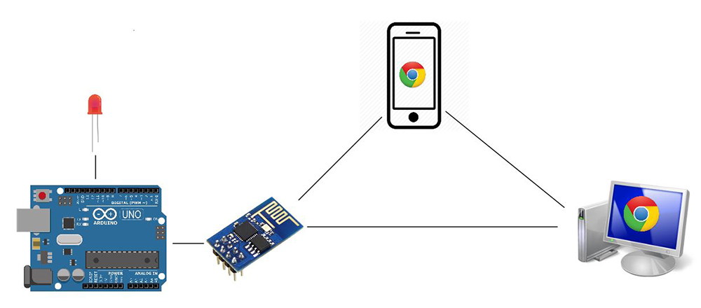
IOT has been all around us for quite some time now and it has almost revolutionized the way machines communicate among themselves. As a starting point here is a simple project tutorial on creating Arduino web server that will help you to open the doors to IOT. In this tutorial we are going to host a simple web server as shown in the above image.
Remember you can host a webpage in your ESP8266 but the controlling functionality is pretty less in it. Given that there are only two GPIO pins in it. Also it doesn’t have of PWM, timer and other options. ESP866 serves as a communicating medium which enables Arduino to join a LAN. We can use our WiFi enabled mobile phones/ laptops to form a LAN with Arduino. From our devices we will access the Arduino web server, fetch the webpage from it and control the modules or components connected to it. I have made a video explaining this entire tutorial – please do check that out
COMPONENTS REQUIRED:
Arduino Uno
ESP8266 WiFi module
LEDs
Connecting wires
Birdirectional Logic converter
Mobile or Laptop or other WiFi enabled devices
QUICK BRIEF ABOUT ESP8266:
I presume most of us are familiar about ESP8266 chip. For those who are not aware of it, ESP8266 is a versatile low cost WiFi chip that is capable of providing WiFi connectivity to your embedded projects. It can work in both Station and AP mode which makes it a perfect choice for IOT projects. Apart from this it also has two GPIO pins which can do some basic turning ON/OFF.
USAGE IN CREATING ARDUINO WEB SERVER:
In this project the whole purpose of ESP8266 is to provide a WiFi link between Arduino and our mobile device. We are creating a Local Area Network (LAN) by using ESP8266 as Station and connect it to Mobile/ Laptop (WiFi enabled devices) which serves as AP/Hotspot. Any devices connected to this AP will be within this LAN ( i.e ESP8266 + Arduino and Mobile devices ). Therefore they can communicate with each other and access the Arduino web server. In order to do all this we should program Arduino to feed a specific set of AT commands to ESP8266.
AT COMMANDS:
Predefined AT commands will decide all the parameters of WiFi link in ESP module. Using this we can control the way ESP8266 make or release the connection with other WiFi devices. This includes Setting AP password, Joining AP’s, Creating server and so on. Refer this link for “Complete AT command list” used in ESP8266
In return to the input AT commands, ESP8266 will acknowledge with response codes which indicate whether the input AT command was accepted or declined by the device. This whole command input and response will be transmitted via Serial communication /UART.
To keep this simple, for majority of commands ESP8266 will respond with given Input command followed by the characters “OK\r\n”. For example if we send the command AT then the ESP response will be
AT\r\n \r\n OK\r\n
This is common response for most of the commands. There are also other response codes that we would need to monitor for this project, which will be discussed later in this article.
ERROR DETECTION AND RECOVERY:
ESP8266 modules can be very buggy and it can be very prone to errors while working with Super fast Arduino. Considering this we need to write the code in such a way that Arduino can detect error response from ESP modules. In order to do that we need to check for appropriate response from ESP module for every Input command.
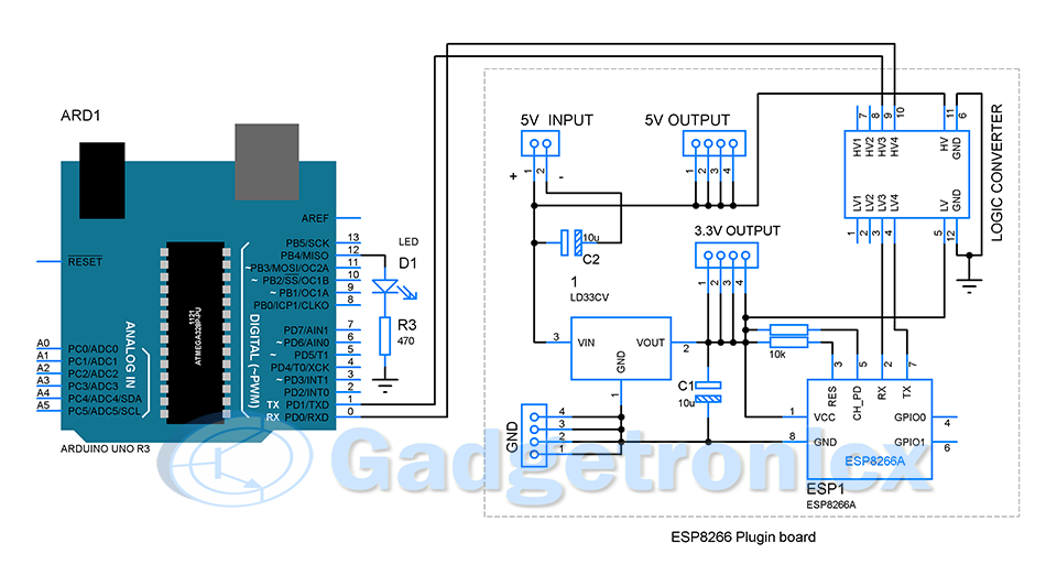
SCHEMATIC DIAGRAM:
From the above schematic diagram, you can see that Arduino is connected to a Bidirectional Logic converter LG1 which basically converts the logic from 5v to 3.3v and vice versa. This is to help both Arduino and ESP module to identify the logic 0 and 1 in order to communicate with each other via UART. Apart from that the schematic diagram is pretty straight forward. The headers in the Plug-in board section is for providing easier connectivity for ESP8266 when using it with Arduino or any other developmental boards.
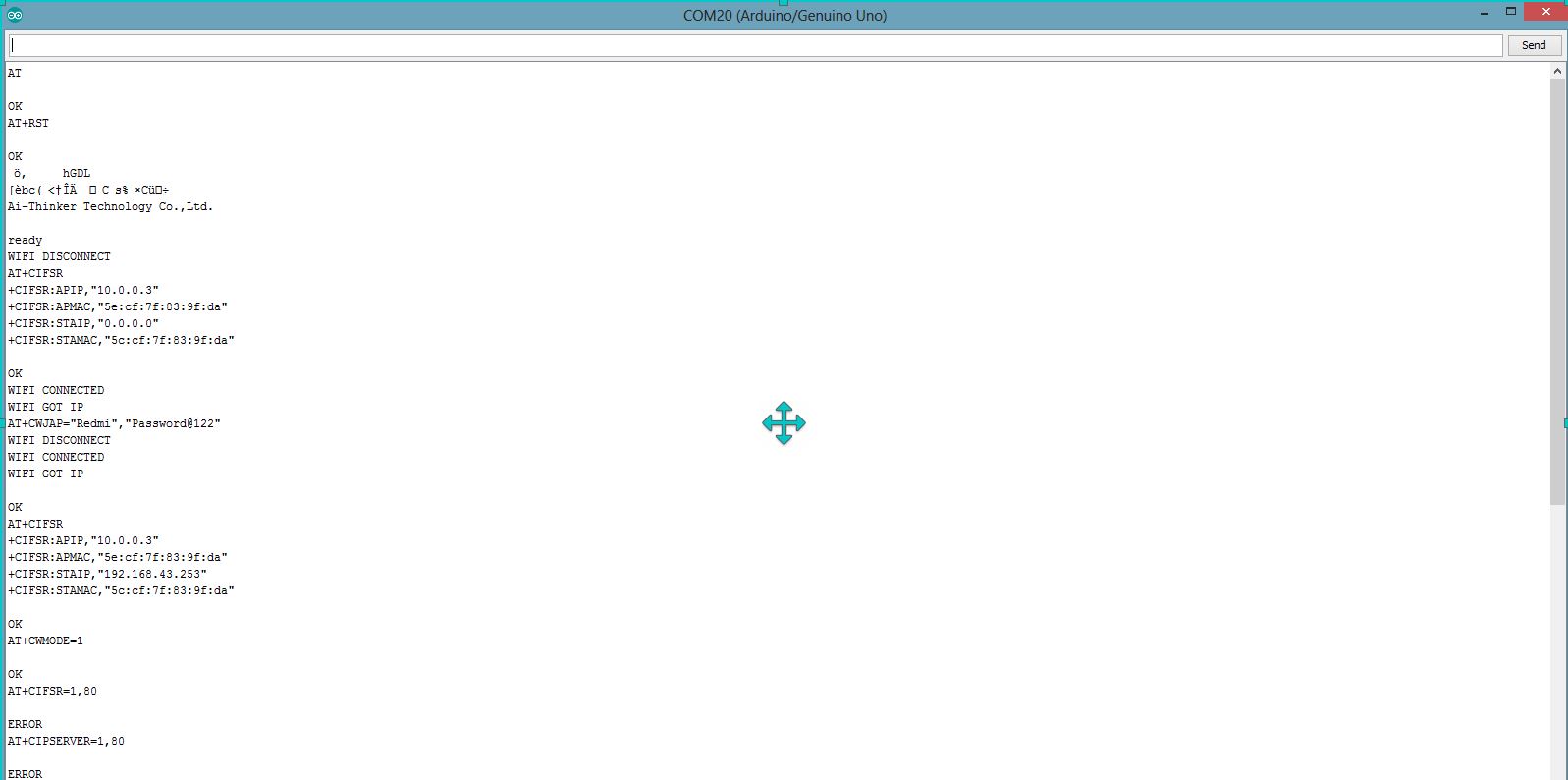
TESTING YOUR ESP8266:
I strongly recommend this step since ESP8266 can be buggy and it’s quite necessary to have this tested. Upload the bare minimum code to the Arduino and connect the ESP8266 as shown in the schematic. Once done use the following commands, but remember to select “Both NL & CR” & Baud rate as 56700 which is default baud rate used by ESP module.
AT – OK
AT+RST
AT+CWMODE=3
AT+CWJAP=”SSID”,”Password”
The above command will make your ESP8266 to join the network you wish and it will remember the AP even after powered down. This is important in terms of this project because the code is developed in an assumption that ESP8266 was already connected to AP or hot spot of mobile device which we will use. This is because connecting to AP through the code seems to make things complex with no considerable benefits to this project.
AT+CIOBAUD=9600
This command is to alter the baud rate at which the ESP module operate. I had to do this since ESP modules worked better with this baud rate than higher speed.
PROJECT WORKING:
Arduino web server can be accessed by the devices within that LAN to control the LED’s or other components. ESP8266 will remember the AP’s that it has been connected to previously. It will get connected to AP as soon as hotspot in your device is turned ON. Once connected, a LAN will be created. Once Arduino detects a connection via ESP8266, it will start sending commands to ESP module to create a server. I have added a LED to indicate server creation. Mostly it will take about two seconds from the moment ESP is connected to WiFi AP.
Once the Arduino web server is ready, open any browser in the devices connected to the LAN and access the IP address assigned to ESP8266 module. Arduino will send a piece of HTML code to the client via ESP module and a webpage will be displayed on your device browser. HTML codes from the Arduino were built to display button in the webpage. Using these buttons user can feed input back to Arduino. Based on the received inputs, Arduino will activate/deactivate LED’s or any other devices that are connected to it.
ESP COMMANDS USED FOR CREATING ARDUINO WEB SERVER:
These are the list of commands that we are going to use to create this Arduino web server.
“AT+RST” – Reset the ESP8266 module
“AT” – Response check
“AT+CIPMODE=3” – Set the module as both Station and AP
“AT+CIPMUX=1” – Setting to allow multiple connections
“AT+CIPSTA=<Local IP address>” – Assign any local IP address but make sure it is compatible with your device.
“AT+CIPSERVER=1,80” – Creating server with port 80
“AT+CIPSEND=<connection ID>,<Byte count>
CHOOSING IP ADDRESS:
I manually set a static IP to my ESP8266 module even though my mobile DHCP will assign IP when connecting with it. I am doing this to make sure I know the IP address of ESP device and I can connect to it without any problem. Without doing this DHCP in my mobile phone will assign IP address which is currently free and you will not know this while using this. But you should take care when choosing your IP address since local IP address differs from device to device. I have read in a documentation that Android phones are programmed to use 192.168.x.x to assign for the devices connecting with it locally. So I have used the IP 192.168.43.253 to assign for ESP module. So search in internet for the IP your devices will use and add it in the code.
HTML WEBPAGE:
So now the server is created in ESP8266. When I am saying server is created, it means that ESP8266 is ready to take client request (that is the browser). Remember ESP module serves only as a communicating medium here, so it’s the Arduino here that respond with the HTML webpage when a client request is detected.
<!DOCTYPE html>
<html>
<body>
<h1>Welcome to Arduino LED control Wizard</h1><p>
You can turn ON/OFF LED connected to Arduino using the buttons given below</p>
<p><b>TURN ON</b> <a href="ON"><button>ON</button></a></br></p>
<p><b>TURN OFF</b> <a href="OFF"><button>OFF</button></a></br></p>
</body>
</html>
ALGORITHM:
Input “AT+RST” command and wait until ESP8266 connects with AP.
Check for “IP\r\n” in the last four characters of ESP response, this indicate that WiFi got IP.
Once connected start feeding the commands to activate the server mode in ESP8266
Monitor the response for each input commands.
Proceed with the next command once the last four characters of response is “OK\r\n” throughout the Server sequence commands.
Force Arduino to wait for the client request from any browser connected within the LAN.
Once request is received check for connection ID provided by ESP8266 and add it to the command “AT+CIPSEND”
Check for the character ‘>’ in the response string from EP module.
In case of incorrect response repeat step 7.
Once correct response is verified send the webpage HTML code from Arduino through the ESP module to client browser.
Wait until you receive response from ESP8266 module and check for the last four characters “OK\r\n” in the response string. Webpage should have been successfully displayed in the browser now.
Force Arduino to monitor the incoming GET request from Client (button press)
Once client GET request is received check for URL parameters in the request, for example GET: /ON , in which /ON is the URL parameter.
Activate/ Deactivate LED/ other devices or do something based on the URL parameter in the response.
WORKING VIDEO:
CODE:
/*Simple code to create webserver in Arduino and control things within the network
Created by Frank Donald */
char Input_buffer[550];
boolean command_flag=false;
int i,j;
boolean stringComplete=false;
boolean request_processed=false;
boolean WiFiConnect=false;
short int command_count=0;
char send_bytes[]="AT+CIPSEND= ,379\r\n";
boolean client_request=false;
boolean flag=true;
char connection_id;
short int page_input_pos;
void setup() {
pinMode(13, OUTPUT);
pinMode(12, OUTPUT);
digitalWrite(13,LOW);
digitalWrite(12,LOW);
Serial.begin(9600);
delay(5000);
Serial.print("AT+RST\r\n");
delay(200);
while(WiFiConnect==false) //Wait till Connecting to WiFi hotspot
{
serial_check();
WiFiCheck(); //WiFi check subroutine
}
while(command_flag==false) //Looping for commands
{
command_input();
}
clear_buffer(); //Clearing the array
while(client_request==false) //Waitingfor anyclient/browser to initiate the request
{
serial_check();
brow_req(); //sub routine to check browser request
brow_resp(); //sub routine for response from Arduino
}
flag=false;
}
void loop() {
serial_check();
page_input_pos=Search_webrequest(); //Monitor webpage indefinitely
activate();
}
void activate()
{
if(flag==true)
{
if(Input_buffer[page_input_pos]=='O'&&Input_buffer[page_input_pos+1]=='N')
digitalWrite(12,HIGH);
else if(Input_buffer[page_input_pos]=='O'&&Input_buffer[page_input_pos+1]=='F')
digitalWrite(12,LOW);
}
}
void WiFiCheck() //Check whether WiFi is connected
{
if(stringComplete==true&&Input_buffer[j-4]=='I') //Check for the status WIFI GOT IP
{
clear_buffer();
WiFiConnect=true;
delay(500);
}
else
{
clear_buffer();
stringComplete=false;
}
}
int Search_webrequest() //repeated loop to check button inputs from Webpage
{
if(stringComplete==true)
{
for(i=0;i<j-2;i++)
{
if(Input_buffer[i]=='G'&&Input_buffer[i+1]=='E'&&Input_buffer[i+2]=='T')
{
flag=true;
return i+5;
}
}
}
}
void brow_req() //sub routine to monitor the browser request
{
if(stringComplete==true&&request_processed==false) //Checking for presence of char in input buffer and check whether the client request has already processed
{
if(flag==true)
connection_id=(char)Input_buffer[0];
send_bytes[11]=connection_id; //Adding connection ID to the CIPSEND command
Serial.print(send_bytes);
clear_buffer();
delay(1000);
request_processed=true; //Changing the flag to true indicating that Client request is processed
}
}
void brow_resp() //Sub routine to respond to client request
{
if(request_processed==true&&stringComplete==true) //Checking the flag on client request process
{
serial_check();
if(Input_buffer[j-2]=='>') //Checking for the Send data signal from ESP module
{
memset(Input_buffer,'\0', sizeof(Input_buffer));
Serial.print("<!DOCTYPE html><html><body><h1>Welcome to Arduino LED control Wizard</h1><p>You can turn ON/OFF LED connected to Arduino using the buttons given below</p><p><b>TURN ON</b> <a href=\"ON\"><button>ON</button></a></br></p><p><b>TURN OFF</b> <a href=\"OFF\"><button>OFF</button></a></br></p></body></html>");
delay(2000);
serial_check();
//while(command_response_check==false);
clear_buffer();
request_processed=false;
client_request=true;
}
else
{
clear_buffer();
request_processed=false; //If request response didnt turn out successful mark the flags so that another CIPSEND command can be passed
flag=false;
}
}
}
void command_input() //Sub routine for commands to create server using ESP module
{
serial_check();
if(command_response_check(Input_buffer)==true) //Checking the response and Tracking the counts of command to handle in case of error response from ESP
{command_count=command_count+1;}
else
delay(1000);
clear_buffer();
switch(command_count) //Enter commands sequentially in creating server
{
case 0: { Serial.print("AT\r\n");
delay(500);
break;
}
case 1: {
Serial.print("AT+CWMODE=3\r\n");
delay(1000);
break;}
case 2: {
Serial.print("AT+CIPSTA=\"192.168.43.253\"\r\n");
delay(1000);
break;
}
case 3: {
Serial.print("AT+CIPMUX=1\r\n");
delay(1000);
break;
}
case 4: {
Serial.print("AT+CIPSERVER=1,80\r\n");
delay(1000);
break;
}
case 5: {
command_flag=true;
digitalWrite(13,HIGH);
break;
}
}
}
void clear_buffer() //Clearing buffer
{
memset(Input_buffer, '\0', sizeof(Input_buffer));
stringComplete=false;
}
boolean command_response_check(char *a) //Checking for OK Response from ESP
{
if(a[j-4]=='O'&&a[j-3]=='K'&&a[j-2]=='\r'&&a[j-1]=='\n')
return true;
else
{ delay(1000);
return false; }
}
void serial_check() { //Serial char available check
i=0;
while (Serial.available()) {
delay(2);
char inChar = Serial.read();
Input_buffer[i]=(char)inChar;
i=i+1;
stringComplete = true;
j=i;
}
}
NOTE:
The above code can only handle request from one client only, so you cannot use more than one client at a time , also ESP module is capable of handling 4 connections at time which leaves us with 2 client limitations all the time.
LED is here for just an indication you can do some cool stuffs like PWM, Timer, Data receiving and so but of course with tweaks in the code but concept remains the same.
Hi Abun,
Looks like only Arduino is sending the command. Kindly check the connection to ESP8266 and see everything is powered ON. Ideally ESP8266 will reset and send some data.
Hi! Thank you for this project!
It is one of the only projects I found where you control the Arduino from a web app. I am still new with Arduino and I was wondering if you can use PHP instead of HTML? or is there a reason why you use HTML?
Thank you
hi sir, i would like to write a program in esp from arduino to add 5 numbers entered in html page 1 and display the answer in html page 2 like after submit button. so can you give a suggestion(code) how to use the entered number in html page 1 for addition and print in html page 2.
Hi Koreddi,
Am not sure I got the question right. In this tutorial we use ESP merely as a link for Arduino to form a LAN with our Smartphone or other devices. You can code the ESP module to work stand alone but am not sure it can store the code for web page in its memory. Best way is to use Arduino to store both the webpage code and when user request webpage let Arduino serve the first webpage and then take the input process them and insert the output into the second webpage and display them. You need a put a bit of work on your webpage, look for information on building a HTML forms. It should do the trick
Very nice writeup. Truly helpful. I modified the code so that the ESP is the AP, and also to use Software Serial. I get the client request in Arduino from the browser , but for some reason the webpage is not returned to the client. Should you for some reason read this, I could use a pointer or two to get this resolved. Will post details once you respond. Thanks.
Hi Erich,
Yes, Using ESP as AP will simplify it for better. I might need more details on the problem you are facing for me to help. Kindly post them please
hi thanks for your nice explanation , i want to ask you how we can send two command signal at simultaneously like text and number together from the hosting server to the arduino through wifi connection


Hi sir!
I want to control, my smart project by creating own website and also want to write values from my website.
Hey!
I would like to know if I could use this same connection to update the Arduino code.
Making some kind of a CI/CD pipeline.
Thanks for your atention!
Hello. After I upload the entire Arduino code, only the first line “AT+RST” gets printed in the serial monitor. Why is this? Thank you!
Hi Abun,
Looks like only Arduino is sending the command. Kindly check the connection to ESP8266 and see everything is powered ON. Ideally ESP8266 will reset and send some data.
Hi! Thank you for this project!
It is one of the only projects I found where you control the Arduino from a web app. I am still new with Arduino and I was wondering if you can use PHP instead of HTML? or is there a reason why you use HTML?
Thank you
Hi,
Glad you liked the project. Unfortunately am not aware of PHP, I have used HTML since it is quite simple to execute and takes less memory.
Hi very interesting project. How to change PORT 80 to another ONE? (changing to xxx it does’n work). thanks. p.
Hi sir. Since it’s not possible to connect multiple users on the same server? What should I use instead of the Esp module?
hi sir, i would like to write a program in esp from arduino to add 5 numbers entered in html page 1 and display the answer in html page 2 like after submit button. so can you give a suggestion(code) how to use the entered number in html page 1 for addition and print in html page 2.
Hi Koreddi,
Am not sure I got the question right. In this tutorial we use ESP merely as a link for Arduino to form a LAN with our Smartphone or other devices. You can code the ESP module to work stand alone but am not sure it can store the code for web page in its memory. Best way is to use Arduino to store both the webpage code and when user request webpage let Arduino serve the first webpage and then take the input process them and insert the output into the second webpage and display them. You need a put a bit of work on your webpage, look for information on building a HTML forms. It should do the trick
Very nice writeup. Truly helpful. I modified the code so that the ESP is the AP, and also to use Software Serial. I get the client request in Arduino from the browser , but for some reason the webpage is not returned to the client. Should you for some reason read this, I could use a pointer or two to get this resolved. Will post details once you respond. Thanks.
Hi Erich,
Yes, Using ESP as AP will simplify it for better. I might need more details on the problem you are facing for me to help. Kindly post them please
hi thanks for your nice explanation , i want to ask you how we can send two command signal at simultaneously like text and number together from the hosting server to the arduino through wifi connection