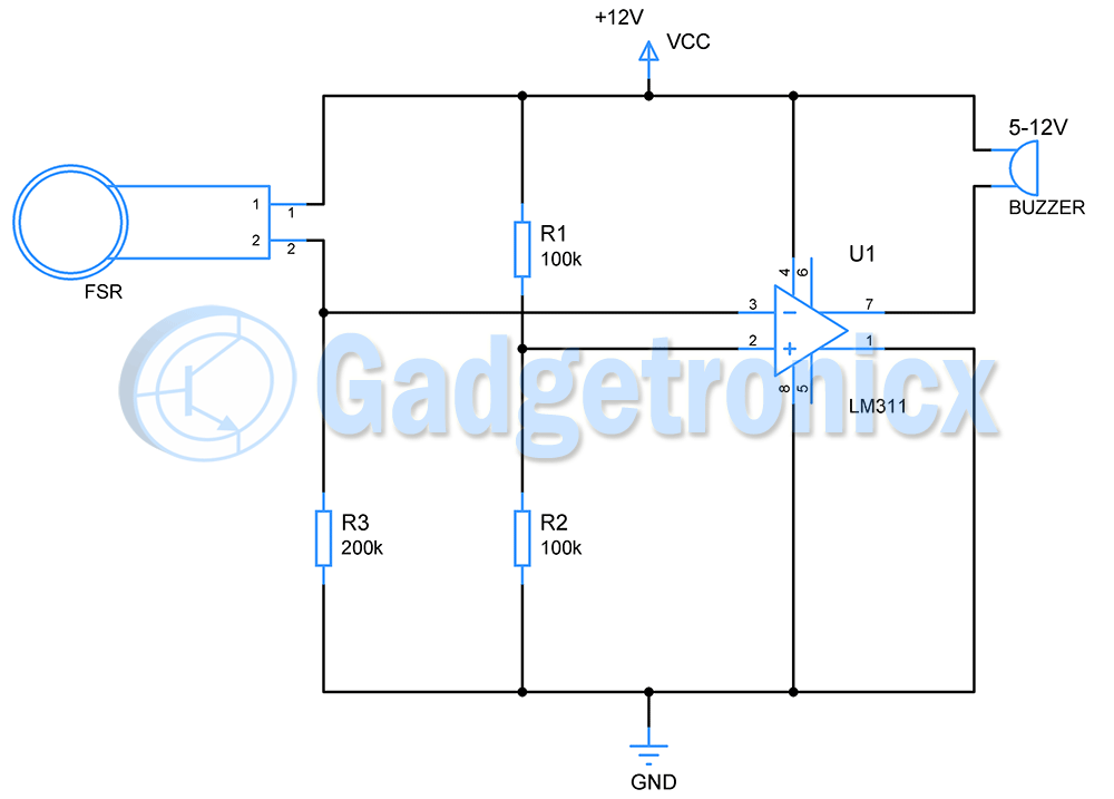
Many of us are familiar with traditional office call bell that is used to alert assistants or other colleagues. It doesn’t have to this boring setup. Here is a simple circuit that can be used as an alternative to this desk call bell. This circuit uses FSR ( force sensing resistor ) as an activator instead of a button and this provides the touch activation feature. A buzzer will act as the sounding element here.
Components Required:
Force sensing resistor
Buzzer – 5 to 12V
Comparator – (LM311)
Resistor(100k) – 2
Resistor (200k) – 1
Force sensing resistor:
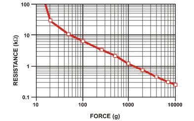
FSR is a resistor whose resistance varies when a force or pressure is applied. When there is no force applied, it offers infinite resistance theoretically. This will be usually in the range of 2 Mega ohms as per the datasheet.
When force is applied on FSR its resistance will decrease. This property will help to sense the variations in force, in our case it will help to sense the force from any finger. The above graph clearly shows how resistance drops when force applied on it increases.
WORKING OF OFFICE CALL TOUCH BELL CIRCUIT:
The FSR is used with another resistor to form a voltage divider. The input from this voltage divider is connected as input to inverting input of comparator. Use comparator chip for this purpose not Opamp. Learn about the difference between Opamp and comparator. Because of its varying resistance the input to the comparator varies with applied force.
The non inverting input is connected to another voltage divider whose output voltage to comparator will be constant. If the input at inverting input of the comparator is more than its non inverting input, output will be low. Whereas if the input at inverting input of comparator is less than input at non inverting terminal then the output will be high.
Let us assume the resistance of FSR is 2M when no force is applied on it. Using voltage divider formula Vout = ( Vcc x R2 ) / ( R1 + R2 ) the input to inverting terminal of the comparator will be given as 1.091V and voltage to non inverting terminal will be 6V.
Vout from FSR and R3= (12 x 200 x103 )/(2 x 106+ 200 x 103)
= 1.091V
Vout from R1 and R2 = (12 x 100 x 103) / (100 x 103+ 200 x 103)
= 6V
So the output of comparator will be high which will be close to 12V. As there is no difference between the voltage at buzzer terminals no current flows through it, therefore buzzer will not sound.
Case 2:
Let us consider a user is applying force on FSR with his thumb. The resistance FSR now drops to say 30Kohm ( looking at the FSR resistance graph) . Now the voltage from FSR and R3 changes from 1.091V to 10.435V. This is fed to inverting input of comparator.
Now the input voltage to non inverting input is 6v. Now the output of comparator will be low (i.e. 0V). Now there is difference between the voltages at buzzer terminals and the current sinks to 7th or output pin of comparator through buzzer. Therefore the buzzer will deliver a loud sound.
The buzzer will remain active as long as force is applied on FSR.
WORKING EXPLANATION:
Note:
To set this up the resistance value of FSR should be measured with multimeter when no force is applied, here we have assumed that as 2Mohm
Repeat the same by pressing FSR with your thumb.
These resistance will help you to fix the values of resistor R3, R1 and R2 based on the above voltage divider calculation.
LM311 is capable of providing source/sink current of 50mA, here buzzer operates at about 20mA. You can use a transistor switch in the output of LM311 if you intend to use buzzer or speaker that draws high current.
Hope this circuit was useful. Have a look at our circuits library for more circuits. Leave your comments, queries and feedback in the comments section below.

 When force is applied on FSR its resistance will decrease. This property will help to sense the variations in force, in our case it will help to sense the force from any finger. The above graph clearly shows how resistance drops when force applied on it increases.