Accelerometers are sensor that is used to measure acceleration of itself or the object where the sensor is fixed to. It is capable of measuring acceleration occurring due to external forces applied and also gravity. This Acceleration sensing alarm circuit will sound the alarm when the object to which it is fixed exceed a certain acceleration level. We can use this circuit in vehicles, toys, even as a wearable for controlling acceleration. You can find other Alarm circuits in our website here.
ACCELERATION SENSING ALARM:
ADXL337 IC:
ADXL337 is a 3 axis accelerometer sensor which is used in our circuit to measure the acceleration in our circuit. This sensor is capable of measuring acceleration levels on X, Y and Z axis and respective acceleration ranges are give via the output XOUT, YOUT and ZOUT pins. Applications of this chip includes gravity sensing, Tilting of portable devices, measuring object speed and vibration. This sensor is capable of measuring acceleration from a range of -3g to +3g. Also remember this sensor should be only used with 3v. Check out ADXL337 datasheet to know more about it.
WORKING OF CIRCUIT:
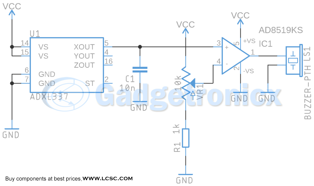
ADXL337 is the heart of this circuit to measure the acceleration of the object. Connect the GND and the Voltage Supply (3V) to ADXL337. The ADXL337 has 3 outputs to differentiate in which axis the object is accelerating. In our circuit the point of interest is only on X-axis ( horizontal ) so we have used only Xout pins. But we can use any of the other two outputs to measure a different axis or even we can use multiple outputs.
When the object starts to accelerate the sensor ADXL337 will translate it by means of analog output voltage in Xout. The Output voltage will depend on the acceleration applied and has a range from 0.1V (Minimun acceleration) up to 2.8V (Maximum acceleration). The output from XOUT goes to non inverting input of OpAmp comparator. On the inverting input we use a 10k potentiometer to feed reference voltage using POT VR1. This will help you to set the acceleration point where exceeding it will force the output of Opamp to high state and sound the buzzer. By this way the circuit will sense the acceleration and sound the alarm when exceeds the limit.

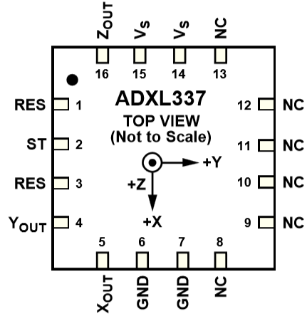 ADXL337 is a 3 axis accelerometer sensor which is used in our circuit to measure the acceleration in our circuit. This sensor is capable of measuring acceleration levels on X, Y and Z axis and respective acceleration ranges are give via the output XOUT, YOUT and ZOUT pins. Applications of this chip includes gravity sensing, Tilting of portable devices, measuring object speed and vibration. This sensor is capable of measuring acceleration from a range of -3g to +3g. Also remember this sensor should be only used with 3v. Check out ADXL337 datasheet to know more about it.


