Sensor activated switches or lighting circuits are quite easy to build and will come in handy with plenty of applications. In this article we will see how to build a force or pressure switch for AC appliances and Force activated LED lights. These circuits has applications such as theft alarms, Auto room lighting, Pressure monitor and so on.
FSR or Force Sensing Resistor:
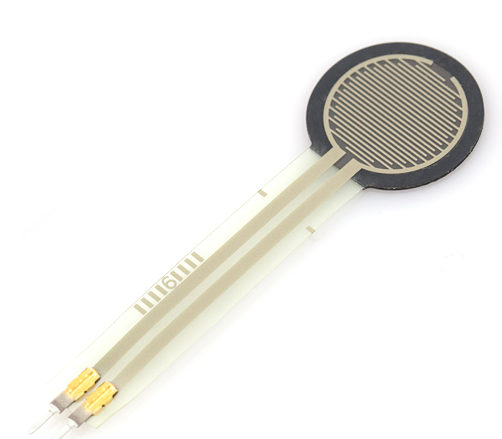
So to build a force or pressure switch circuit we need a sensor. And that is what FSR or Force sensing resistor is all about. FSR is typically a resistor which exhibits different resistance values when pressure or force is applied on it. This article explains the construction of FSR and I believe It will give a better idea on how it works. But the bottom line is when no pressure is applied on this sensor it exhibits infinite to high resistance ( in the range of Mega ohms ). But as soon as pressure is applied on FSR resistance drops to 100k ohms. This will drop even further to 100 ohms when high pressure is applied on to the sensor plate.
Working of Force / Pressure switch:
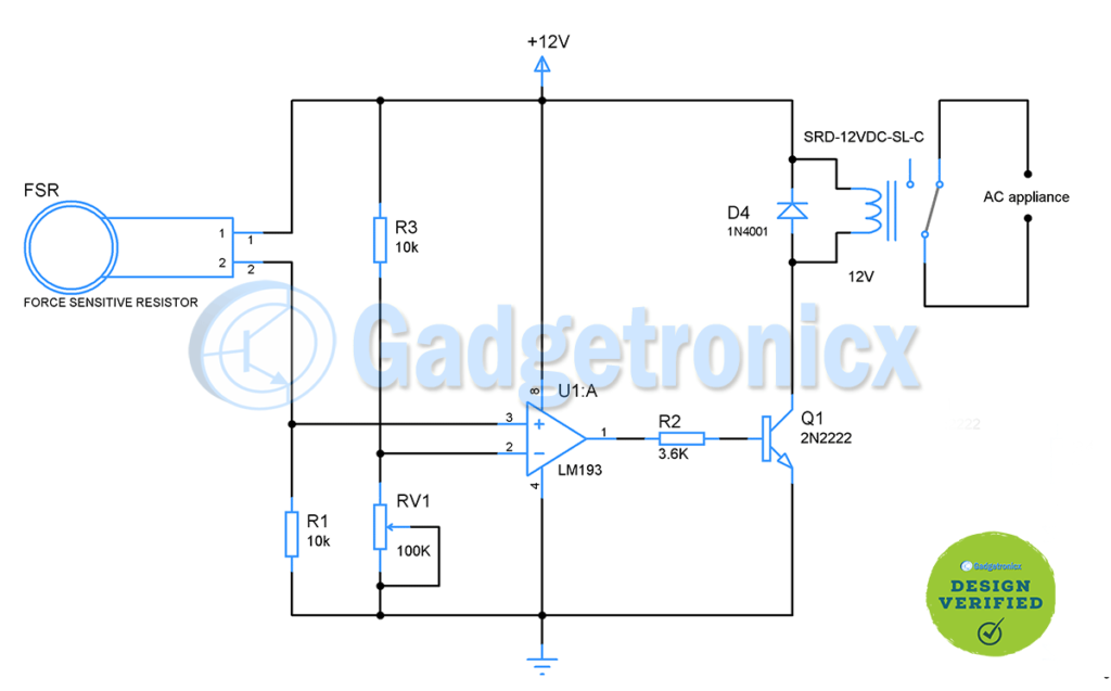
The working of this circuit starts with FSR sensing the pressure applied to its plate. The FSR is connected in series with resistor R1 to form a voltage divider. The voltage output from this voltage divider pair is fed to Non inverting input of comparator. On the other hand another voltage divider pair is formed using Resistor R2 and variable resistor R3. The output voltage from this voltage divider is fed to inverting input of comparator. Variable resistor is meant to adjust the triggering voltage or pressure at which the above circuit should activate.
When no pressure is applied, voltage output from the FSR and R1 pair will be low comparing to output voltage of R3 and RV1. When pressure is applied to FSR its resistance drops thereby output voltage from divider pair will increase. Now voltage at non inverting terminal will be high than inverting terminal. This force the output voltage of comparator to high activating the transistor connected to it as a switch.
Next comes the 12V relay which is used to activate any AC appliance under 12A current rating. The output of IC LM193 is so low to activate the relay hence I have used famous 2N2222 to activate the relay. Diode D4 acts as a protection element for rest of circuit from the reverse current which flows as soon as relay gets turned off.
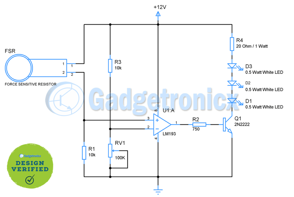
This is another variant of the Force activated switch where I have used three high power 0.5 Watt LED’s in the output stage. 0.5 Watt LED’s will be pretty bright so this circuit will be perfect to light up your cup board or shelf as soon as you apply some pressure on it. But remember you should add high wattage current limiting resistor ( 1 Watt in our case ) in series with LED’s. This will ensure safe power dissipation through the resistor.
Calibrating the pressure switch circuit:
In order to calibrate the above circuit, measure the output voltage from voltage divider made up of FSR and R1 after you apply pressure on FSR which you intend to fix as a trigger point for your circuit. Now set the voltage output of divider R2 and R3 little lower than the above voltage. Now your circuit will trigger the lights or relay whenever appropriate pressure is on FSR.
Note:
Keep in mind that comparator chip LM193 can drive load only upto 20mA so usage of transistor switch is advisable for load which consumes more than 20mA.
You can modify the output stage ( transistor, relay , LED’s ) to suit the application of your need.
Calibration is quite important for this circuit to work so perform proper calibration using POT RV1 before using it.
Hope this circuit was useful to you. Do try this circuit and let us know your feedback or experience. If you have any queries or suggestions please leave them in the comment box below. Also check out our other sensor circuits in our website. Happy DIY 🙂