Switches are of several types and we are using almost every type in day-to-day life. Mechanical switches, wireless switches and much more helps us to activate device with ease and also provides safety. Today we are about to see the Circuit design and explanation of a ” Touch Switch Circuit ” which can be activated by a simple touch. Sounds so easy to use isn’t it , also it is easy to build.
WORKING OF TOUCH SWITCH CIRCUIT:
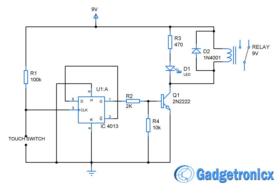
The circuit was built around a simple Flip Flop IC CD4013 which is of edge triggered means it is capable of changing its output state when there is a sudden change in input clock levels. The switch part comprises of two simple pieces of wire or conductor which must be placed with gap between them.
When the touch switch is not closed the Pull up resistor R1 pulls the Clock line to logic high “1” state. When user touches the switch the skin contact closes the circuit therefore the Clock pin of the Flip flop will be now pulled down to zero that is ground potential. The Flip flop was wired in such a way to toggle the output states with each touch activation by the switch.
When the switch was initially activated by a touch the Flip flop gives logic 1 as output and this in turn activates the transistor Q1 to drive the relay. This relay in turn activates the device connected to it. When the switch is triggered for the second time the Flip flop changes its output state giving logic low 0 which in turn deactivates the transistor Q1 and relay connected to it. Protection Diode D1 was added to prevent the reverse flow of current when the relay is turned off.
NOTE:
This touch switch circuit suits for any device activation but must be re designed to tolerate the load current.
Pull Up resistors and Pull down resistors are used in order to avoid false triggering of the circuit.
Hi Amssma,
To avoid debounce pull up resistor was added in the circuit, it serves the purpose of feeding clock as well. Try placing the two wires close to each other, so your finger will make fine and steady contact between wires.


I had bounce issues when testing this circuit how did you made your touch switch?
Hi Amssma,
To avoid debounce pull up resistor was added in the circuit, it serves the purpose of feeding clock as well. Try placing the two wires close to each other, so your finger will make fine and steady contact between wires.
Hello
Thanks For You
pretty cool circuit gonna try this out
Sugumar,
Glad to hear that.