
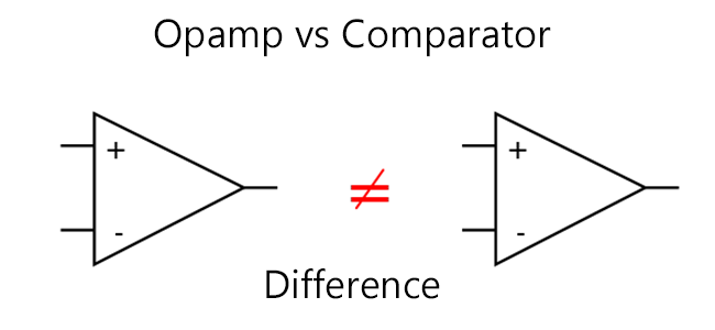
Opamp or Comparator, what should I use in my design? This is one common question that many electronics enthusiasts will often come across. There always tend to be some confusion between these two components and often engineers mistake that these both mean the same. A comparator is not an OpAmp and you should not confuse them! This article ” Opamp vs Comparator ” is meant to point out the key differences between these two components and how these two should be used appropriately in a design.
OPAMP VS COMPARATOR:
A comparator is for comparing analog voltages. Its output is either low (in case the voltage on the IN+ input is less than on the IN- input) or it is high (as long as the IN+ voltage is higher than the IN- voltage). But it is low or high a digital output! It is finally a 1Bit analog to digital converter. This is important to keep in mind!
OUTPUT STAGES:
To understand this better, we want to look at some typical output stages:
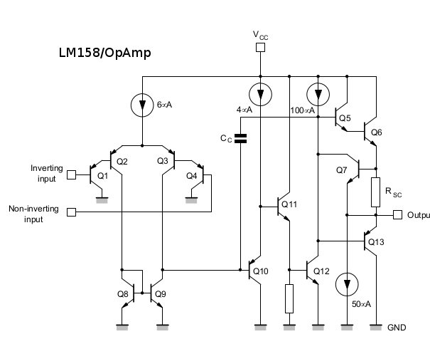
Figure 1: LM158 – OpAmp (source: ST Micro datasheet)
Q6 and Q7 are a typical analog push-pull-output stage. You can also see, that you will not get to the positive rail (Vcc), because there is always a voltage drop over RSC. For some digital logic families, this might not be enough for a proper high level.
Now let’s have a look at a comparator
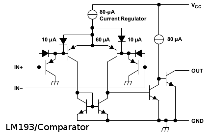
Figure 2: LM193 – Comparator (source: TI datasheet)
When you look at the output, you see, that is an open collector output (it always requires a pull-up resistor!). Depending on the pull-up and the load, you will get almost the whole voltage swing (from GND to VCC).
The input stage of both, the OpAmp and the Comparator are somehow quite similar Yes, they are about analogue voltages.
OTHER DIFFERENCES:
Beside the output stage, the OpAmp is designed for a closed loop operation. You will always have a feedback transistor between the output and the IN– input. Finally, the circuitry in between is quite a bit more complicated. The behavior of an OpAmp in open loop applications is not predictable. It is definitely not recommended. The power consumption might increase a lot, especially when using a rail-to-rail OpAmp (that would have a decent voltage swing up to Vcc). Also, the response time is not really determined and might vary a lot. If your project goes mass production, this is really bad news! Some devices might work (typically the prototypes work perfectly), some might not and nobody knows, why except you 🙂 Because you will not confuse an OpAmp and a comparator after today.
A comparator is designed for an open loop operation. Saturated output transistors are great for a comparator. There is no feedback resistor to the IN– input. Never do that! It is not made for that! The comparator has a low response time and a high slew rate. Yes, perfect for a digital output! So, you see although the symbol looks the same, an OpAmp and a comparator are very different components. It doesn’t happen often, that a designer uses a comparator instead of an OpAmp, but the opposite is seen quite often. Good, that this will not happen to you (anymore).
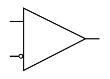
Comparator symbol as used by TI
Hope this tutorial helped you to understand that Opamp and Comparator are two different components and possess a different operational method. So next time you shouldn’t have problem in choosing Opamp vs Comparator. Happy learning 🙂


“Q6 and Q7 are a typical analog push-pull-output stage”. You mean Q6 and Q13 are a typical analog push-pull-output stage
“You will always have a feedback transistor between the output and the IN– input”. You mean feedback resistor