
Modern electronic circuits comprises of IC’s of different logical families working together to do the task. Than foremost challenge when working with chips of different logical families is the logical incompatibility. This means Low logic output “0” from a 5v TTL family might be interpreted as High logic “1” by chips that belongs to CMOS family. This problem might lead to a catastrophic circuit failure. To deal with this we use special circuits called as Logic level converters. These circuits are capable of converting 5v to 3.3v and 3.3v to 5v successfully thus bridging the chip TTL and CMOS chip families. In this article we are about to see a Logic level converter which converts 5v to 3.3v and vice versa.
COMPONENTS REQUIRED:
- N-channel MOS-FET
- Resistors 10k Ohm
- Diode
- Battery 5V
- Battery 3.3V
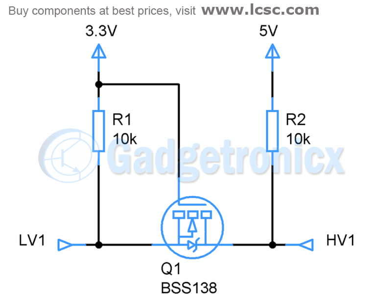
WORKING OF LOGIC LEVEL CONVERTER CIRCUIT:
This converter can pass from high to low and/or low to high. Here we use a couple of pull-up resistor to realize bi-directional level shifting. We connect the inputs voltage in each terminal of the MOSFET as it’s shown in the schematic.It consist of a N-channel enhancement MOSFET, the gate is connected to the lowest supply voltage and the source is connected directly to the low voltage input pin. The drain is connected to High Voltage input pin with a Pull up resistor pulling the pin to logic 5v.
In this case that the MOSFET substrate hasn’t internally connected with the source it must be done externally. The diode between the drain and the source present a n-p junction as a barrier. This allows to safely connect devices in each output without any issue. In the above circuit the pins LV1 and HV1 serves as both input and output pins. Therefore if you need to convert 3.3v to 5v, you supply 3.3v to LV1 pin which gives 5V output in HV1 pin and vice versa. When there is no input fed to the input pin output at the other pin remains at 0v.
Hope this circuit was useful to you. Checkout our Circuit diagrams page from more useful circuits. Leave your comments or feedback in the below section.


