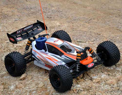
Remote control Cars also known as RC cars are something every electronic hobbyists would love to build. But most of them didn’t know where to start and how to build it, some even got deceived by its complex looks. This article is focused to guide hobbyists to build their own homemade RC car with minimal components.
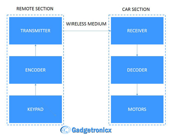
BLOCK DIAGRAM:
To build a RC car we need to make sure that these blocks are available. The above blocks are divided into two sections Remote and Car for the purpose of understanding. Starting from Keypad which controls the movement of the Car whereas Encoder and decoders are meant to encode and decode the movement signals for secured transmission. Also transmitter sends the movement signals through wireless medium and receiver fetches the signals for the destination.
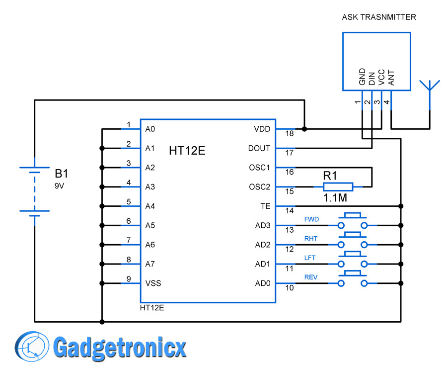
CIRCUIT DIAGRAM OF REMOTE CONTROL:
The above Remote control Circuit consists of three important components Keypad, Encoder IC HT12E and a RF Transmitter RF433 module.
KEYPAD: The Keypad for our remote is made up of four individual buttons which is wired to the data pins of the data pins AD0 to AD3 of the encoder IC. When these buttons are pressed it passes the movement signals to the encoder,
ENCODER HT12E: This encoder serves the purpose of encoding the movement signals fed by the individual buttons. The Data pins AD0 to AD3 is active low hence pressing the button closes the circuit and a logic 1 or high signal is fed to these pins. It also contains Address Pins A0 to A7 which allow us to try out different address combinations for secured transmission of data but make sure you use the same address combination in the receiving end (decoder). In the above circuit we did’t try out any address combinations hence all the pins are grounded. The Dout Pin gives the encoded output data. Read more about the Working of HT12E Encoder.
RF433 TX: This is a simple RF433 TX module which operates at frequency at 433MHz. The encoded data from the Encoder is fed into DIN pin of the TX and a simple antenna is attached to its 4th pin.
OSCILLATOR FREQUENCY: The Oscillator frequency of HT12E is 3.25Khz ( refer the oscillation frequency vs supply voltage graph in the datasheet ). This frequency is fixed using the resistor R1 ( 1.1M ) . Modifying this resistor value will alter the output frequency.
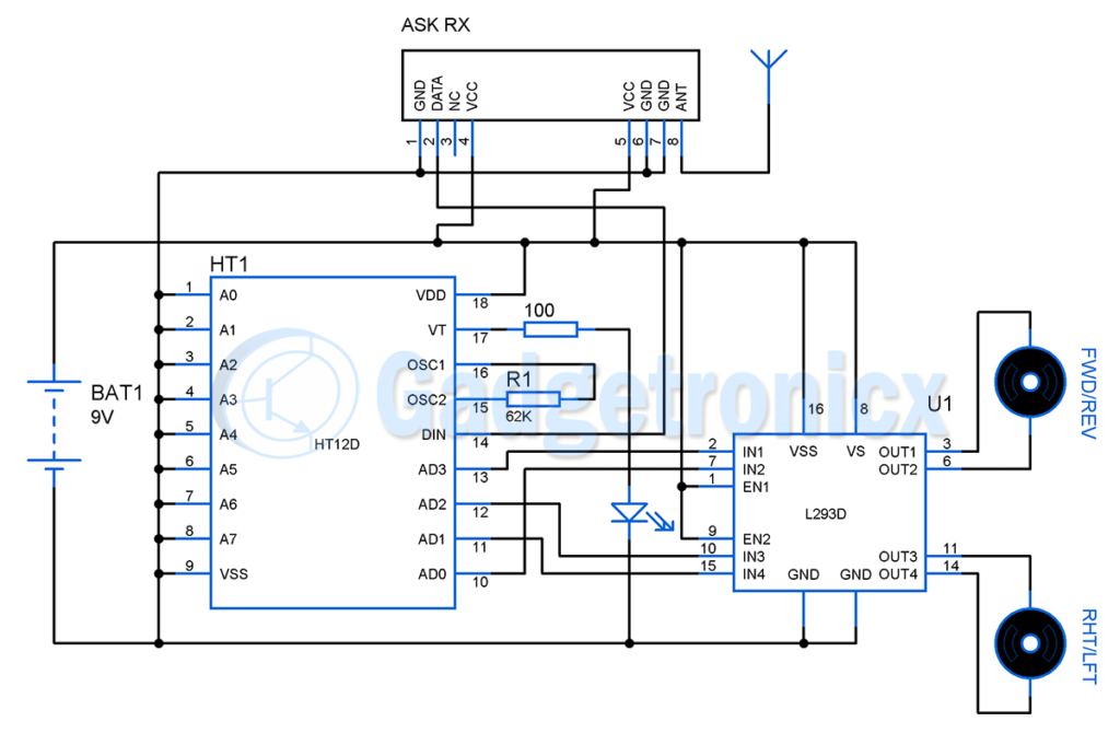
CIRCUIT DIAGRAM OF REMOTE CAR:
RF433 RX: This a simple RF433 RX module which operates at 433MHz. The received encoded data signals is received through the antenna and the signal is obtained from DATA pin to feed the decoder.
HT12D DECODER: The encoded signals from the RX module is fed into the DIN pin of the decoder. The signal is then decoded by the decoder, remember to use the same address combination used in the encoder if any otherwise the movement signals will be interpreted incorrectly. The decoder also consists of VT pin which serves as a identification if any RF link is established, LED was connected to this pin for identification.
OSCILLATION FREQUENCY: For successful reception of incoming signal and decode them, the HT12D oscillation frequency should be 50 times the encoder oscillation frequency. In our case HT12E oscillation frequency is 3.25Khz, hence our decoder oscillation frequency should be 162.5Khz. Fixing the value of R1 as 62K does this job ( refer the oscillation frequency vs supply voltage graph in the datasheet ).
L293D: This IC serves as a Bidirectional motor driver. It is highly impossible to drive heavy loads such as motors using decoder IC hence we have used a dedicated L293D IC for this purpose. Read more about the Working of L293D.
MOTORS: Two simple DC motors are used for the movement of RC Car. A motor for moving the Car forward and backwards whereas the other one is used to steer the car left and right.
MOVEMENT MECHANISM OF RC CAR:
We are done with the Remote control and the circuits which is about to be placed inside the car. Now next important thing is provide mechanism to move our RC car front and back. Fix a gear to the motor and to the rail which connects the rear wheels. Fix the motor close to the gear in the rail so that when motor makes a movement the car moves forward. Likewise when the motor rotates in the opposite direction the car should move backwards.
STEERING MECHANISM OF CAR:
Steering mechanism is bit tricky than the movement mechanism since it requires bit of mechanics. There are several Steering mechanisms used in building RC cars but here i prefer to use “Rack and Pinion” arrangement to steer the car in our desired direction.
Image Courtesy : www.offroaders.com
The above animation shows the working of Rack and pinion steering mechanism. Here the pinion gear will be attached to our front motor which is responsible for Right/left steering. So when this motor moves in clockwise direction the car turn left and vice versa. See the working this gear arrangement in this video.
PARTS NEEDED:
RF433 MHz TX and RX
Encoder HT12E and Decoder HT12D
L293D – 1
Motors – 2
Wheels – 4
Resistors – As required
LED
Hope this project was informative to you. Check out other Electronic projects in our website. If you have any feedback or comments about this project do leave them in the below comments section.
Dhanushka,
Yes, you can. The pins in this 8 pin module seems to be duplicated and the 4 pin module has all the sufficient pins for this circuit to work. A little help here http://www.expertcore.org/viewtopic.php?f=18&t=3547
Hi Frank! i need your help asap, i bought remote control car and replaced its circuit with the one i built based on this article..now, i cannot make the car moves…hope to hear from you very soon because my presentation on this upcoming monday..
Bhushan,
You can find RC parts online for sure. Try searching it internet the prices might differ, i have listed some parts in the article itself you can buy them too its from amazon.in


can I use this transmitter and receiver kit because receiver has 4 pins.It has not 8 pins.
http://www.lankatronics.com/modules-and-sensors/rf/433mhz-rf-transmitter-and-receiver-kit.html
Dhanushka,
Yes, you can. The pins in this 8 pin module seems to be duplicated and the 4 pin module has all the sufficient pins for this circuit to work. A little help here http://www.expertcore.org/viewtopic.php?f=18&t=3547
Hi Frank! i need your help asap, i bought remote control car and replaced its circuit with the one i built based on this article..now, i cannot make the car moves…hope to hear from you very soon because my presentation on this upcoming monday..
Fionaa,
It should work, can you describe the problem bit briefly or consider testing your circuit block by block.
Frank,
I made this car but I didn’t see a output.
Shaluka,
What problem you are facing?
Plz frank!
Hey Frank
In the rc car circuit can i supply 6V directly.(by 4 cells)?
Yes you can but use 6v motor with it. Also make sure your power supply is capable of sourcing enough current to drive the whole circuit.
Hello
I want to make it
Is ready made parts are available in market
Like remote & all
So I can but them & make it by joining them
As the car in above picture
& how much money required for it
Pls tell me
Bhushan,
You can find RC parts online for sure. Try searching it internet the prices might differ, i have listed some parts in the article itself you can buy them too its from amazon.in
What resistors we’ll need to this project?
Frank.What are the required resistors for this project? 1.1M and what else?
SH,
100 ohms, please take a look at Schematic for the components used.
Please Frank
Hi Frank
Can you give me The RF433 TX and RX Circuite please
I want to make it myself … Please