Who doesn’t love playing with RC cars and Robots. Not only playing, engineers and enthusiasts like us love to build and experiment with these stuffs. Also its fair to say that RC’s and Robots have became more than just toys, they already have started to integrate into our life slowly. But to take this to another standard we have built a Gesture controlled car using the most powerful development board Arduino. Let’s see how to build your own gesture controlled car.
MOTTO OF GESTURE CONTROLLED CAR:
To drive a toy car using our hand movements or gestures.
HARDWARE USED:
TRANSMITTER PART AND ROBOT:
Arduino Uno.
ADXL335 accelerometer.
434 MHz RF transmitter.
Breadboard.
RECEIVER PART AND ROBOT:
Arduino Uno.
434 MHz RF receiver.
L293D motor driver IC.
Chassis and wheels.
2 DC motors.
Breadboard.
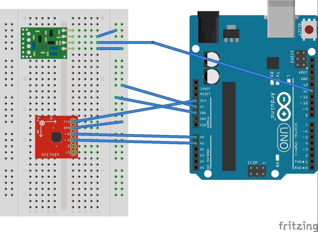
SCHEMATIC DIAGRAM OF TRANSMITTER:
ADXL335:
This forms the basic constituent of our gesture controlled car. This basically is an Accelerometer which is capable of detecting acceleration in three axis X,Y and Z. The output of these three axis can be obtained separately from three pins x,y and z. This is shown in the above circuit diagram (I have used only X and Y axis for this project) . Read briefly about interfacing this sensor with Arduino here.
ARDUINO UNO:
The arduino board in the transmitter part acts as an interpreter. This fetches X and Y values from the accelerometer and then decides the gesture. There are five gestures or movements we have used in this project. By trail and error method we have recorded the X and Y values for the gestures, those are
Stop or No Movement – X-Value:331 to 339 & Y-Value:341 to 349
Tilt Forward or Forward movement – X-Value:376 to 384 & Y-Value:336 to 344
Tilt Backward or Backward Movement – X-Value:301 to 309 & Y-Value:351 to 359
Tilt Left or Left movement – X-Value:291 to 299 & Y-Value:276 to 284
Tilt Right or Right movement – X-Value:316 to 324 & Y-Value:386 to 394
Based on the above conditions the Arduino will decide the movement and send it to transmitter.
433MHZ TRANSMITTER:
This is one of the popular plug and play RF module which comes with a RX pair. It transmits the command received from Arduino and transmit it to rx module at a frequency of 433Mhz.
//Connect the Transmitter data pin to Arduino pin 12
int xPin=0;//Connect x pin of adxl335 to pin A0
int yPin=1;//Connect y pin of adxl335 to pin A1


int ledPin=13;//led on pin 13 is ON except when transmitter is parallel to the ground


#include <VirtualWire.h>


void setup()
{
  vw_setup(2000);//Bits per second
  pinMode(ledPin,OUTPUT);
  Serial.begin(9600);//Initialise the serial connection debugging
}

void loop()
{
  int xval=analogRead(xPin);
  int yval=analogRead(yPin);

  Serial.print("xval=");
  Serial.println(xval);

  Serial.print("yval=");
  Serial.println(yval);

  delay(1000); //used to display values after 1s delay

  Serial.print("\n");

  if ((xval>330 && xval<340) && (yval>340 && yval<350)) //stationary or stop(transmitter parallel to ground)
  {
    digitalWrite(ledPin,LOW);
    send("s");
  }
  else
  {
    if ((xval>375 && xval<385) && (yval>335 && yval<345)) //forward(transmitter tilted forward)
    {
      digitalWrite(ledPin,HIGH);
      send("f");

    }
    if ((xval>300 && xval<310) && (yval>350 && yval<360)) //backward(transmitter tilted backward)
    {
      digitalWrite(ledPin,HIGH);
      send("a");

    }
    if ((xval>290 && xval<300) && (yval>275 && yval<285)) //left(transmitter tilted to left)
    {
      digitalWrite(ledPin,HIGH);
      send("l");
     }
     if ((xval>315 && xval<325) && (yval>385 && yval<395))//right(transmitter tilted to right)
    {
      digitalWrite(ledPin,HIGH);
      send("r");

    }
  }
  delay(1000);

}


void send(char *message)//send function definition
{
  vw_send((uint8_t *)message, strlen(message));
  vw_wait_tx(); // Wait until the whole message is gone
}
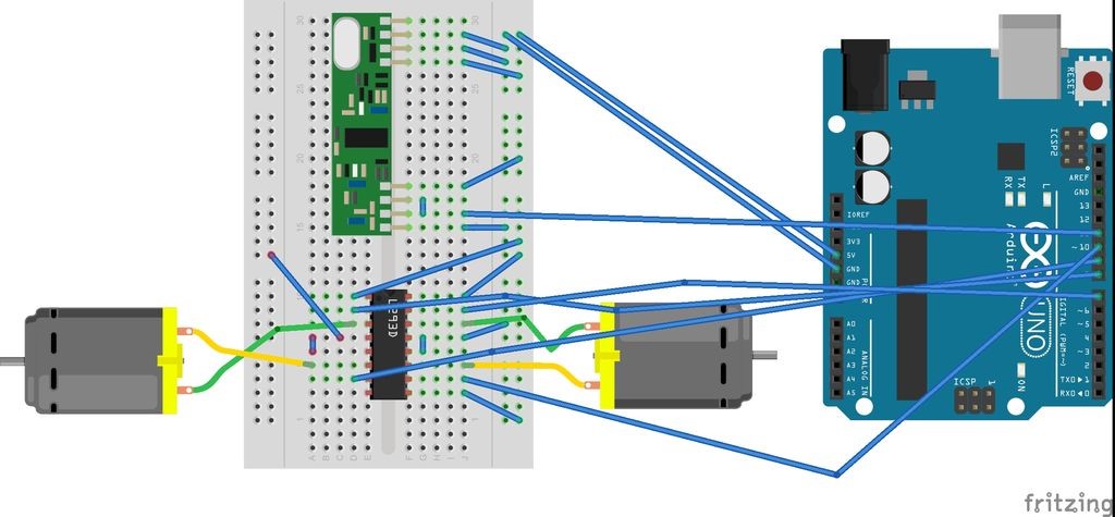
SCHEMATIC DIAGRAM OF RECEIVER:
RF RECEIVER:
This is a matching pair of TX used in the transmitter part o this project. On receiving the bytes from Transmitter it sends the data to Arduino for further procesesing.
ARDUINO:
The data from the Receiver is used for interpretation of movements. Once interpretations Arduino commands the motor to move in appropriate directions, There are five possibility of data values from the receiver and each data is interpreted as follows.
Character ‘s’ or 0x73 – Stop
Character ‘f’ or 0x66 – Forward
Character ‘a’ or 0x61 – Backward
Character ‘l’ or 0x6C – Left
Character ‘r’ or 0x72 – Right
Once the interpretations are made Arduino operates the motor accordingly.
L293D & MOTORS:
L293D is a motor driver IC which is used since Arduino cannnot provide enough current to drive a motor. Two motors are used to take care of all the movements ( Forward, Backward, Left and Right)
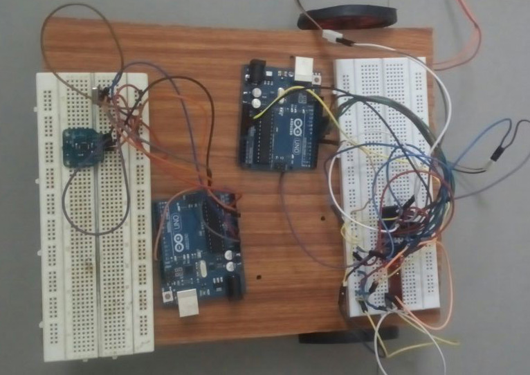
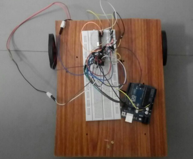
COMPLETE SETUP OF RECEIVER AND CAR:
CODE FOR RECEIVER PART:
//Connect the Receiver data pin to Arduino pin 11

#include <VirtualWire.h>
byte message[VW_MAX_MESSAGE_LEN]; // a buffer to store the incoming messages
byte messageLength = VW_MAX_MESSAGE_LEN; // the size of the message
int lm=12;//pin 12 of arduino to pin 9  of ic
int lmr=8;//pin 8 of arduino to pin 2 of ic

int rm=10;//pin 10 of arduino to pin 10 of ic

int rmr=7;//pin 7 of arduino to pin 15 of ic
int ledPin=13;//led on pin 13 is ON except when bot is stationary

void setup()
{
 Serial.begin(9600);//Initialise the serial connection debugging

 pinMode(ledPin,OUTPUT);
 pinMode(lm,OUTPUT);
 pinMode(lmr,OUTPUT);
 pinMode(rm,OUTPUT);
 pinMode(rmr,OUTPUT);

 vw_setup(2000); // Bits per sec
 vw_rx_start(); // Start the receiver
}
void loop()
{
    uint8_t buf[VW_MAX_MESSAGE_LEN];
    uint8_t buflen = VW_MAX_MESSAGE_LEN;

    if (vw_get_message(buf, &buflen)) // Non-blocking
    {
   int i;
Serial.print("Got: ");//debugging

   for (i = 0; i < buflen; i++)
   {
      // Serial.print(buf[i],HEX);//You may also use integer values debugging
       //Serial.print(' ');// debugging

          if (buf[i]==0x73)//Stationary
          {
            digitalWrite(lm,LOW);
            digitalWrite(lmr,LOW);
            digitalWrite(rm,LOW);
            digitalWrite(rmr,LOW);

            digitalWrite(ledPin,LOW);
          }
          else
          {
            if(buf[i]==0x66)//Forward
            {
              digitalWrite(lm,LOW);
              digitalWrite(lmr,HIGH);
              digitalWrite(rm,HIGH);
              digitalWrite(rmr,LOW);

              digitalWrite(ledPin,HIGH);
            }

            if (buf[i]==0x61)//Backward
            {
              digitalWrite(lm,HIGH);
              digitalWrite(lmr,LOW);
              digitalWrite(rm,LOW);
              digitalWrite(rmr,HIGH);

              digitalWrite(ledPin,HIGH);
          }

            if (buf[i]==0x6C)//Left
            {
              digitalWrite(lm,LOW);
              digitalWrite(lmr,LOW);
              digitalWrite(rm,HIGH);
              digitalWrite(rmr,LOW);
              digitalWrite(ledPin,HIGH);
            }

            if (buf[i]==0x72)//Right
            {
              digitalWrite(lm,LOW);
              digitalWrite(lmr,HIGH);
              digitalWrite(rm,LOW);
              digitalWrite(rmr,LOW);
              digitalWrite(ledPin,HIGH);
            }
           }
     }
     //Serial.print("\n");// debugging
        }
        //delay(1000)
}
WORKING VIDEO:
APPLICATIONS:
Gesture controlled car or Robots can be used in military and tactical units to save lives.


 car at home")


Sir where to attach battery of receiver and transmitter
Where do we have ro attach the power supply to run motors if i am using 12 v battery?
project is work or not?
Jaimin,
Yes it will work
any rf pair that work beside the 433 mhz
Allen,
You can choose any communication medium you want provided MCU should not faster than the communication medium takes
where do i download the VirtualWire.h library
Here you go -> https://github.com/m0/Updated-Arduino-VirtualWire-Library