IR remotes can be problematic sometimes and I know the feeling of being frustrated when your remote is malfunctioning. So in this article we are going to help you with a circuit that can help you to test your IR remote easily. In this circuit we are using a IR photo-transistor as IR sensor for receiving signals from remote and then use an LED indicator to the state of Remote. This will be particularly useful to shop vendors who sell IR Remotes in their shop.
COMPONENTS REQUIRED:
IR Photo Transistor
5V Voltage regulator
LED
Resistor 330 Ohm
Battery 9V
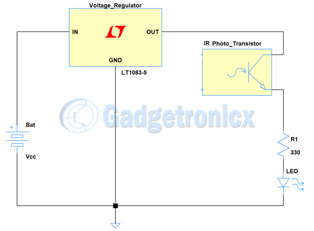
WORKING OF IR REMOTE TESTER CIRCUIT:
First we use a voltage regulator to supply 5v to the above circuit. If you have ready 5v supply ready you can avoid the regulator. I thought to design this circuit portable so powered using a 9v battery. Here for the purpose of detecting IR signals we have used an IR Phototransistor. Generally Phototransistor is a component that acts similar to a transistor switch but instead of current at the base it requires incident light to turn ON. But when comes to IR Phototransistor it consists of a special lens that reduces the interference of other light source to its base making it to react only to IR signals.
When you are using a Remote IR beam of some frequency will hit the Phototransistor which activates the Phototransistor and turns the switch ON. This allows the current from Collector to flow to Emitter through the base and activates the LED connected to it. Thus when Remote button is pressed Output LED turns ON and when button is not pressed LED remains in OFF state acting as Remote tester. Connect the all the grounds between them, battery, voltage regulator and LED.
Hope this IR remote tester circuit was helpful to you. Check out our Circuits Library for more circuits collection 🙂


 RF Remote control circuit")
 car at home")