Stereo Amplifiers are quite handy in places where we need to amplify the input signals to make it audible for all. Whether it is for a party, a meeting, or just to listen to full Hi-Fidelity, this amplifier will do a perfect job. This Stereo amplifier circuit is easy to build and will provide amazing audio power and extremely low total harmonic distortion. It is much cleaner than anything I have seen on the market using standard audio IC’s.
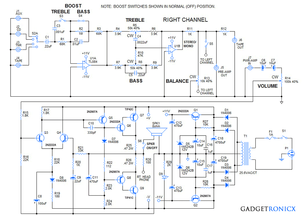
STEREO AMPLIFIER CIRCUIT DIAGRAM:
WORKING DESCRIPTION:
The pre-amp section uses two op-amps, U1A and U1B to provide treble and bass boost at low volumes and treble and bass controls for tailoring the sound to the user’s preference. Selector switch S2A is a 2P4T, ( 2-pole, 4-throw (position)) rotary type to select from one of four line level inputs, (AUX, CD, TUNER, TAPE). They are coupled to U1A via C1, R1. Switches S3 and S4 are DPDT (double pole, double throw) slide switches that select for treble and bass boost.
As shown, they are in the OFF (no boost) position. R2 and C2 are shorted out by S4 canceling the bass boost. S1 is open which defeats the treble boost. R1 and R3 form a unity gain invertor/buffer and feed the signal to the treble/bass control network of U1B. If switch S3 is closed, then C3 is in parallel with R1 and boosts the treble gain at a break frequency of 2.34 KHz. If switch S4 is opened, then the feedback loop has an additional gain 16, and a low pass break frequency of 234 Hz.
The tone circuitry, Treble and Bass are enabled via U1B and the feedback network R4 – R9 and C4, C5. The Bass control has a break frequency around 190 Hz and a gain of around 16 db. The Treble control has a break frequency around 1500 Hz and a gain of 15 db. The output of U1B is connected by R11 to the balance control which has a grounded wiper. This decreases or increases the output of the Right and Left channels in an opposite manner to balance the signal level of a common input to both channels.
Resistor R11 connects to J5, the Pre-Amp Output jack and through R12 to J6, the Tape Output jack. Jack J7, is the Power-Amp input jack. A jumper cable must be connected from jacks J5 to J7 to pass the Pre-Amp signal to the Power-Amp. If desired, an effects processor, graphic equalizer or other audio processor can be inserted in the signal chain between jacks, J5 and J7, to further enhance the signal. Switch S5, when closed, combines the Right and Left channels for Mono operation. This is useful for a single channel mic input, or mono input, to enable sound to come out of both speakers, (Right and Left).
The Power-Amp circuit amplifies the line level signal at jack, J7, to power the 8-ohm Speaker. The signal is passed through C6, C7, which are wired to form a 5 uF non-polar capacitor, to the volume control, R14. The wiper of R14 passes the desired signal level through R15 to the positive input, (base of Q3), of the power op-amp stage.
Q3 and Q4 form the differential input pair of the power op-amp. D8, C8, R18, and R19 isolate the negative voltage rail and act as a current source to transistors, Q3, Q4. Transistor Q5, performs as a level shifter to drive the quasi-complimentary, cascode output pairs formed by transistors Q6, Q7 and transistors Q8, Q9 respectively. Diode D7 and R22 provide the correct bias voltage separation to provide about 10 to 20 mA of idle current through the output stage transistors and resistors R25, R26. This ensures that there is no cross-over distortion in the output signal, because the cascode output transistor pairs are actively conducting at the crossover transition.
Capacitor, C11 and resistors, R23, R24, form a bootstrap bias network that provides the negative bias to cascode transistor pair Q8, Q9, during the negative half cycle of the signal waveform. The Power-Amp stage gain is set by R21, R20 and C9. Except for frequencies lower than 8 Hz, C9 can be ignored in the GAIN equation.
Thus a .5 volt peak input voltage will yield a 17 volt output peak voltage which is ideal for the +/- 18 VDC supply. Transistors Q1, Q2 are connected as emitter follower voltage regulators to supply +/- 11 volts to the TL084 pre-amp IC.
LED D9 and current limiting resistor R29 indicate when the stereo is ON. The main power supply consists of transformer T1, 25.6 VAC, center-tapped, at 2 to 4 Amps. D1 – D4 form a full-wave bridge rectifier which is filtered by capacitors, C18, C19. Switch S6, Enables or Disables the speakers. Resistor R30 reduces the output before it is connected to the stereo headphone output jack (not shown).
NOTE:
- Only the Right Channel Pre-Amp and Power Amp are shown, the Left channel is the same.
- Use dual controls for Treble, Bass and Volume. Use DPDT slide switches for Treble and Bass Boost.
- A 2P4T (2-pole, 4-throw, position) rotary switch to select sound signal source. Treble and Bass controls are linear taper.
- The volume control is audio taper.
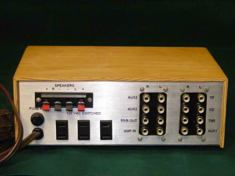
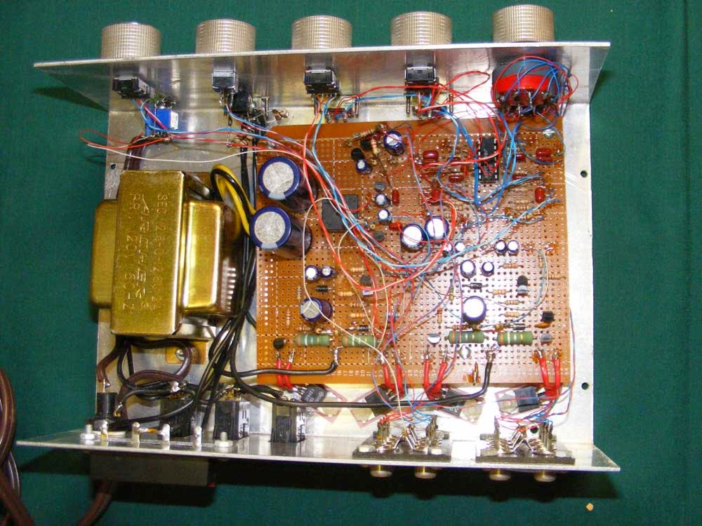
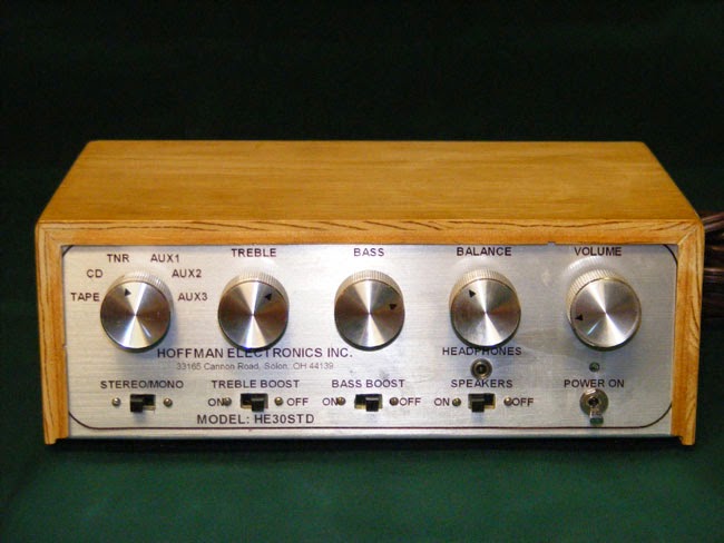
STEREO AMPLIFIER:
 |
 |

Good morning, good afternoon! My apologies for writing now, after it was posted so long ago, but I just discovered this on Pinterest. I think it’s a simple and well-chosen design; I’d be interested in building it, but with a lower power output, say 10W, well, my speakers can’t deliver more than 10WRMS. Which transformer to use? What resistors should I modify for this purpose? What would the power consumption be? What percentage THD does the power amplifier have?
Thanks in advance.
JC.
Hi Ron,
Thanks for the great schematic. I’m really interested in building this. But I do have a few questions for you (FYI – I’m a novice to electronics and I’m working to teach myself a little at a time):
a) What size and type of circuit board do you recommend using?
b) Can your plans be modified to with a different IC chip to increase output (i.e. 50 watts per channel)?
c) Where did you get the metal housing for the project?
d) The pictures suggest that the metal housing is also your heat sink. Is this correct?
Thanks again for your great information. I have read through this multiple times and pick up something new each time I read it!
Don