Diodes are very much versatile in nature and has been considered as one of the key components in Electronics. This is mostly used in Power circuits, Protection circuits, Waveform modifiers, signal conditioners and so on. This is part II of Diode tutorial which explains “how to use a diode“, “What are the common applications of a diode“, “Explanation of how it works in practical circuits“.
This tutorial will be highly effective if you know how a diode works and underlying principles behind it. If you are new to Diode, I would strongly advice you to check out Part I of this Diode tutorial where the working and construction of Diodes are explained in detailed manner tailored to electronics engineering students or enthusiast or anyone interested in basic electronics. For easier navigation I have added links below to jump to your preferred section.
Diodes act like a one sided valve allowing current to flow through only in one direction. Considering this it’s fair to say a diode should be used when you want to block reverse current. Apart from the direction of current there are other factors you should consider when using a Diode in your circuits.
Applied forward bias voltage should exceed forward voltage of diode to force forward current through it (0.7v for Silicon and 0.3 for Germanium diodes)
Reverse bias voltage should not exceed the maximum reverse voltage of a diode or you will end up damaging the diode.
You should not try to force current more than rated maximum forward current in a diode
If the circuit you are building is time sensitive, consider switching time/ transient time of a diode in to account while designing ,since every diode exhibits some capacitance when supplied with AC signal.
APPLICATIONS OF A DIODE:
Diodes is a versatile electronic device and are widely used in Electronic circuits. I have listed most important and widely used areas where diodes play a vital role in functionality of a circuit.
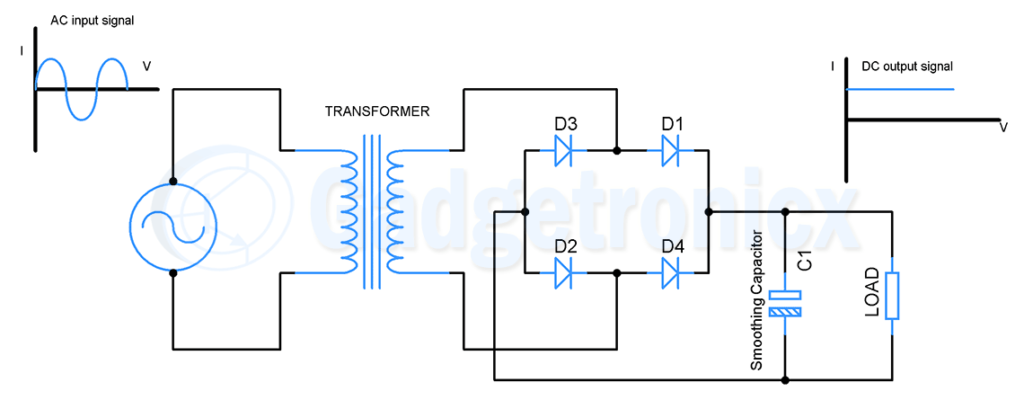
Diodes are the primary component when comes to rectifier. The function of a rectifier is to convert the incoming AC signal to DC signal. Half wave, Full wave and Bridge Rectifier are the three important types when comes to a rectifier. However out of these Bridge Rectifier is widely used since it holds advantage over other types.
The above shown is a Bridge Rectifier circuit. It uses 4 diodes connected back to back to each other. This is widely used in power supplies where it converts the incoming AC signal to DC signal. Out of all the rectifiers Bridge rectifier proved to have more advantages than others so we will take a look at its working here. Working of this circuit starts with AC power supply which goes to a step down transformer to convert the high voltage AC signal to low voltage AC. The stepped down AC signal is then passed through diodes D1, D2, D3 and D4 arranged in bridge configuration.
Here is what happens here, AC signal comprises of positive half cycle and Negative cycle. During the positive half cycle diodes D1 conducts current since it is forward biased and flows through the Load Resistor R and back to the negative terminal of AC power supply through diode D2. Similarly when Negative half cycle of AC signal passes through the bridge rectifier set up current flows through Diode D4 and through the load resistor R. It then goes to Diode D3 back to positive terminal of the power supply. The resultant output signal is shown above. To further convert this pure DC signal a smoothing Capacitor is used. The purpose of the capacitor is to smooth out this output signal so that the output will be a steady DC signal.
There are notable advantages that Bridge Rectifier holds compared to Full wave and Half wave.
Output voltage from bridge rectifier will be about 0.67Vmax of input voltage.
The ripple frequency of output signal will be twice the input frequency which makes it easy to eliminate the ripples using small smoothing capacitors instead of bulky ones.
FLYWHEEL DIODE:
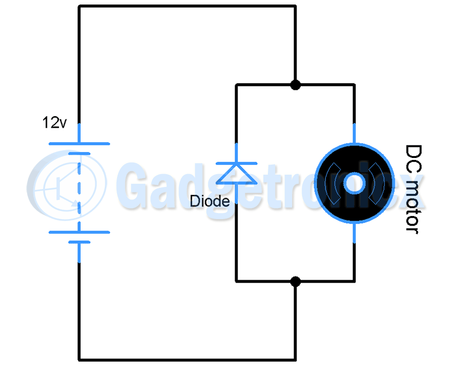
Apparently Diode saves a lot of appliances in your home than you realize. Inductive components like motor, relay generates backward current when they are turned off. This current flows in reverse direction into the circuit which can damage the circuit as well as the appliance.
If you are aware of working of an inductor you would have known Inductor produces reverse current when voltage supplied to it got cut off. When alternating current or AC flows through an inductor it develops a magnetic flux around it. This magnetic flux tries to keep the current flow steady and oppose any change in current by developing a negative emf across Inductor. This property of Inductor comes into play for using a Flywheel diode with inductive components.
In the above circuit, Motor is an inductive device and a Flywheel diode is connected across it. This diode does nothing until voltage is supplied to our motor here. When voltage is cut off current stops flowing and as we know Inductor hates change in current and as a result an opposite emf will be developed across its terminals. In the absence of supplied voltage this induced emf starts forcing significant current to flow into the circuit in reverse direction. This current if allowed into the circuit will damage other components in our circuit.
In this case when you add a Flywheel diode parallel to inductive component. The reverse induced emf will forward bias the Flywheel diode and reverse current starts flowing through the diode. The reverse current continues to flow through the diode until the magnetic flux developed across inductor collapses and induced emf across it becomes zero. In this way diode acts as a protector to other components in the circuit by providing a safe path to reverse current
CLIPPING CIRCUITS:
These are the circuits that is used to modify input waveform and offer voltage protection for circuits. As the name suggests these circuits clip the input waveform to a particular voltage level thereby producing a modified waveform in the output. These circuits works based on reverse bias characteristics of a diode where it blocks the flow of current and therefore the voltage across it’s terminal will be unaltered. Remember this and you can understand the below circuits without any problem.
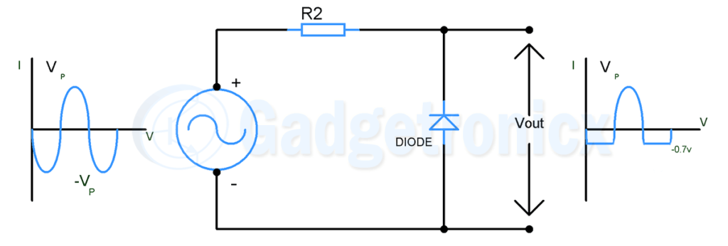
a) POSITIVE CLIPPING CIRCUIT:
The above shown circuit diagram is a Positive clipping circuit. Here an AC signal source is connected to resistor and diode connected in series. During the positive half cycle diode conducts current and therefore only 0.7v which is typical forward voltage of a diode will exhibited in the output. This is because in order for diode to conduct current input voltage should exceed forward voltage. In other terms the signal will be clipped to +0.7v. Meanwhile during Negative half cycle diode will be reverse biased and zero current flows through it leaving the voltage across the terminals untouched. This is how it serves as a positive clipping circuit.
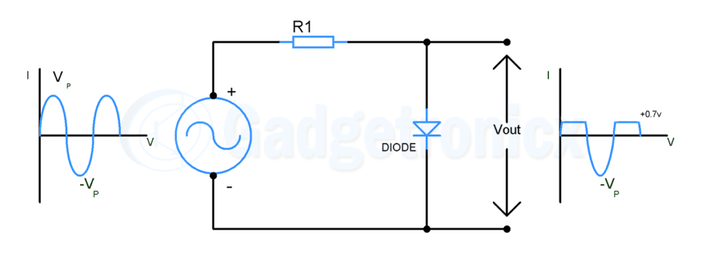
b) NEGATIVE CLIPPING CIRCUIT:
The above shown circuit diagram is a Negative clipping circuit. The direction of the diode here is reversed from what we have seen in Positive clipper. This way when positive cycle of a AC signal is passed through it will be reverse biased blocking current flow and leaving the voltage untouched. Therefore positive cycle will be exhibited in the output. Whereas during Negative half cycle diode will be in forward biased state and current flows through it. Therefore clipping the negative half cycle of signal to -0.7v which is equivalent to its forward voltage.
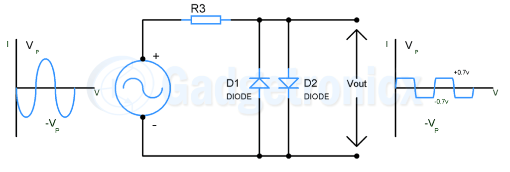
c) POSITIVE AND NEGATIVE CLIPPING CIRCUIT:
The above shown circuit diagram is a Positive and Negative clipping circuit. This is nothing but a combination of positive and negative clipping circuit. Here you can see two diodes placed in parallel to each other but in different direction. When AC signal is supplied diode D1 clips the positive half cycle of the circuit while diode D2 clips negative half cycle of the signal. Thus in output you will see signal which is clipped in both half cycles at 0.7v and -0.7v voltage level.
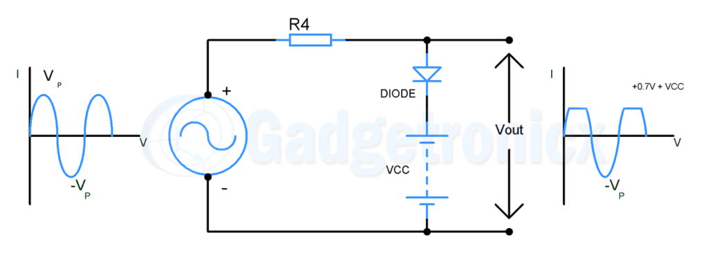
d) BIASED CLIPPING CIRCUIT:
There are times where we need to clip the circuit at a voltage level greater than diode’s forward voltage. In these cases we can uses a voltage source to provide necessary bias and force the clipping voltage to shift to our desired level. In the above circuit as you can observe peak voltage of AC signal is Vp / -Vp and when using a voltage source VCC in the positive clipping circuit, the voltage required for AC signal to force the current through diode will increase from 0.7v to 0.7v + VCC. For example using a 4v source as VCC will clip the positive half cycle at 4.7v voltage level. This will be helpful when we need to limit the signal to a desired voltage level. We can also clip both positive and negative half cycles at our desired level and can clip them at different levels.
CLAMPING CIRCUITS:
This is another circuit using diode which works on input waveform but different from what clipper circuits does. Clamping circuits are used to add a DC level to input AC signals and also to alter the peak voltage of AC signals( both positive and negative peak ) to any desired level. DC level here refers to the 0v point where an AC signal moves from positive half cycle to negative half cycle and vice versa. To simply put the clamping circuits can shift an entire signal up to positive side or to the Negative side.
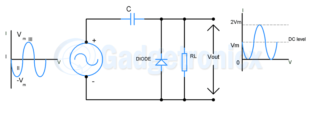
a) POSITIVE CLAMPING CIRCUIT:
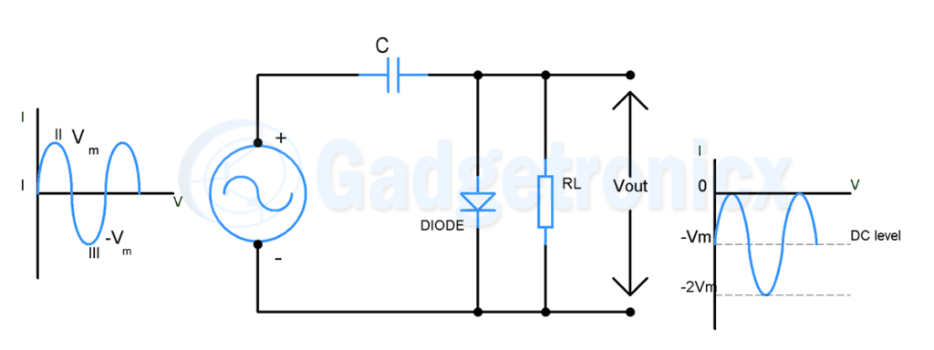
This is the clamper circuit that shifts the input signal to positive side where the lowest peak of input signal will be at zero. Check out the above waveform to get more understanding of what positive clamper circuit does to a typical AC input signal.
Before getting into its working there is a condition that clamper circuit needs to satisfy in order for it to work. The RC time constant of R and C in this circuit should be very large compared to the time period of input signal. Ideally RC time constant should be 10 times greater than time period of input signal.
Here is how it works. When Negative half cycle of an AC signal pass through the circuit, diode will be forward biased and current flows in the reverse direction charging the capacitor to peak voltage of AC signal but in reverse polarity. When signal switches to positive half cycle, the discharge from capacitor will be very less since RC value is large. During the positive cycle diode will be in reverse biased state and zero current flows through it. Since no current flows through diode input signal will be exhibited across RL without any voltage drop. But here the capacitor is already charged in reverse polarity.
Applying Kirchhoff’s equation to the above circuit at this instant will give the output voltage equation as
Vo = Vc + Vi
Where Vc is the capacitor voltage and Vi is the input voltage. The below calculation equates after one full cycle of input waveform and therefore Capacitor will be always in charged state.
Using this equation you can derive the output voltage and plot the output signal.
When input signal is at 0v / I , capacitor voltage is at Vm, output voltage will be Vo = Vm
Position II / -Vm of input signal will result in Capacitor voltage of Vm and in turn will give the output voltage Vo = 0
When input is at position III / Vm, capacitor voltage will be at Vm therefore will give the output voltage Vo = 2Vm
The above voltage values will result in entire signal shifted towards positive side as shown in above graph. The DC level in this signal is shifted to peak voltage of input signal’s positive half cycle peak voltage Vm. Whereas peak voltage of output signal will be twice the peak of input signal 2Vm and lowest peak will lie at zero.
b) NEGATIVE CLAMPING CIRCUIT:
Positive clamper circuit shifts the signal to positive side whereas Negative clamper pushes the entire signal to negative side. The circuit is similar to positive clamper except for diode which is reversed in this. When positive half cycle of AC signal is passed through the circuit diode will be in forward biased condition and allows current to flow through it. In this case capacitor starts charging to the maximum or peak voltage of AC signal. The capacitor will retain this voltage till the diode is forward biased.
Once the signal switches to Negative half of incoming signal the diode will be reverse biased and the input voltage will be exhibited output across Resistor.
Applying Kirchoff’s voltage to the circuit will give the output voltage as
Vo = Vi – Vc
Where Vi is the input voltage and Vc is the capacitor voltage. After the initial complete cycle of input waveform capacitor will be always charged and voltage will always appear across it.
Using this equation you can derive the output voltage and plot the output signal.
When input signal is at 0v / I , capacitor voltage will be at Vm, output voltage will be Vo = -Vm
Position II / Vm of input signal will result in Capacitor voltage Vm and in turn will give the output voltage Vo = 0
When input is at position III / -Vm, capacitor voltage will be Vm therefore will give output voltage of Vo = -2Vm
The above voltage values denotes that the entire signal is shifted to negative side in the output. Here the maximum peak voltage moves from Vm to zero and minimum peak voltage moves from -Vm to -2Vm.
BYPASS AND BLOCKING DIODE:
Growing power demands have created a huge demand for Solar energy and it is fair to say diode makes the usage of solar energy systems possible and efficient. In fact solar cell is nothing more than a photo sensitive diode which generates current when sun light falls on it. But leaving aside the Solar cells usage of regular diodes with solar cells and panels is very much necessary.
BYPASS DIODES:
This a regular diode that is usually connected in parallel with solar cells but in reverse biased mode. Solar cells typically generate about 0.58v per cell and it is connected with other solar cells to generate higher voltage and current. This is how a typical solar panel is made up of. So what happens here is that when a solar cell in a panel becomes faulty or shadow cast on a single cell voltage across that cell drops. This forces the current from properly functioning solar cells to flow into this faulty or shadow casted cell. This forces the faulty cell to heat up and introduces serious power loss. There are also chances that this solar cell will encounter irreparable damage.
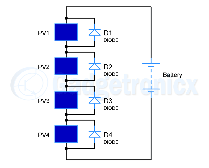
To avoid the above described situation diodes in reverse bias is connected in parallel to solar cell. So what happens here is when sunlight falls on these solar cells, each of these individual cells generate current and voltage of 0.58v is developed across all of it. But when one cell among this series of cells become faulty of shadowed, voltage across the cell drops. Now instead of current flowing into this weakened solar cell, diode connected in parallel forms low resistance path for the generated current to flow through it. This enables all the generated current to flow out of the solar panel rather than going into the faulty cell avoiding huge power loss caused by just one solar cell. And the important thing is a “Schottky diode” a type of diode should be used as bypass ones since it has voltage drop only of about 0.1 to 0.2v rather than Silicon diodes which has voltage drop of about 0.7v
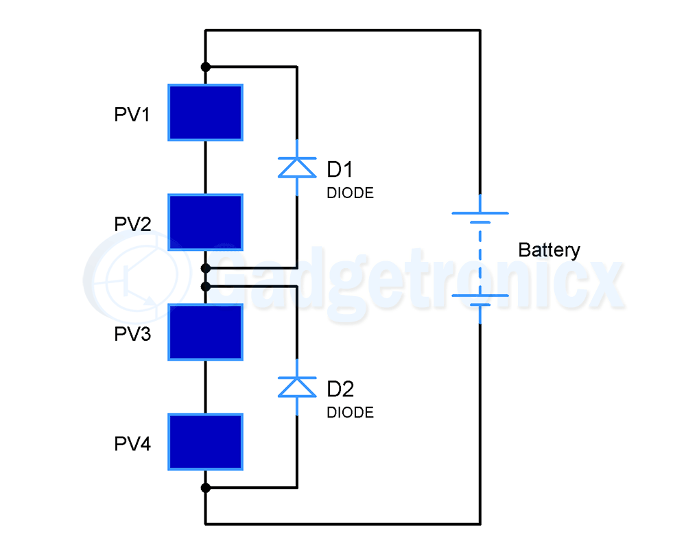
In practical solar systems using one diode per solar cell is not feasible and costly. So instead one bypass diode is used per string or series of solar cells. In that way if any particular string of solar cells gets faulty or shadowed current can flow through the bypass diodes avoiding a greater power loss.
BLOCKING DIODES:
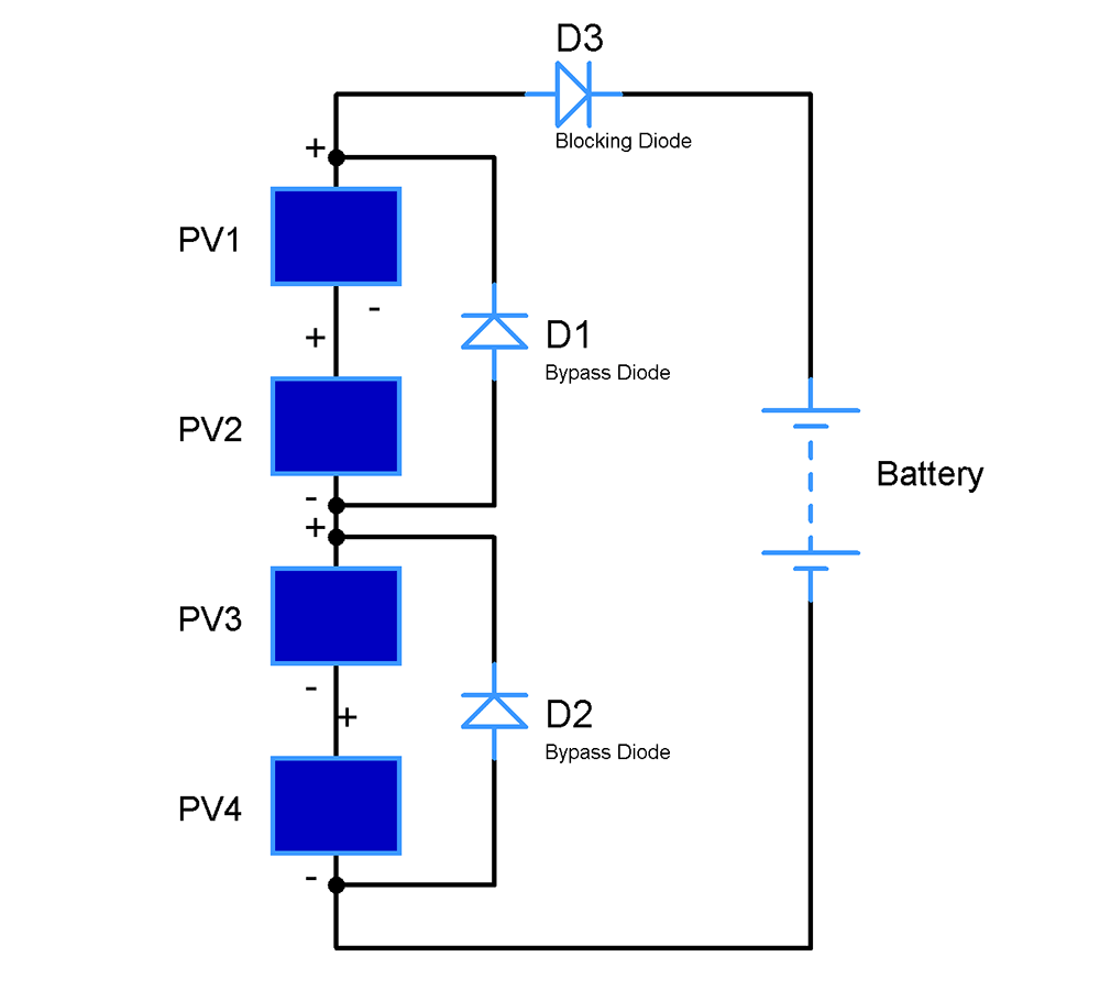
This is pretty much similar to bypass diodes in terms of functionality. Also it is widely used with solar panels and battery powered projects. In most solar systems Solar panels are used to generate current and that current is used to charge a battery. The current from the battery is later used when needed ( refer the below circuit). The problem with this kinda setup is when sunlight falls on panel it develops enough voltage across it to charge the battery. On the other hand when shadow struck or night falls in the voltage across the panel will be zero and in this moment battery connected to the panel tends to have more voltage across it. As a result it will force reverse current into the solar panel which will spoil the solar panel and cost serious money.
In order to avoid the above scenario a diode is added in series with the solar panel. As you know diode allows current only in forward direction when solar panel generates current it allows through it without resistance. When shadow cast over panel or night falls in battery will try to force current back into the panel. In this instant diode will block the incoming current and save the solar panel. It also avoids the accidental discharge of battery. While choose a blocking diode always remember that maximum battery voltage should not exceed the reverse voltage rating of diode
Diode reverse voltage > Maximum voltage of battery
the battery current will surpass the diode spoiling both the solar panel and diode.
This concludes the part II of this Diode tutorial. Hope this tutorial taught you on how to use diodes in a circuit and practical applications of it. If you are looking to learn about basics of a Diode, its construction and working, checkout this tutorial on “Diode : Construction and working operation”
This tutorial is part of our “Electronic components tutorial series” that we have been publishing in our website. Here are some of the other tutorials that will be helpful to you.
Hope the above tutorials will help you to get better in Electronics. Kindly follow us through our Social media channels Facebook, Instagram, Pinterest, Twitter and subscribe to our Newsletter to get all updates regarding the circuits, projects and tutorials published in our website. Happy learning 🙂