Vibration detectors aka vibration meters are devices that is capable of detecting vibrations and display the intensity of vibrations to the user. These vibration meters are commonly used to measure vibrations in a building, roads and other structures. This article covers making of a vibration meter that shows the intensity of vibrations using LEDs. This circuit uses Piezo electric transducer as sensor to sense the vibrations.
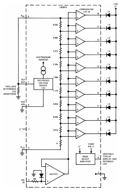
The circuit uses LM3915 IC (click here to get data sheet of LM3915). LM3915 is a led driver chip which is capable of supplying steady current to LED and eliminates the need for resistors. The LM3915 is an 18 pin DIP. In which pin 10 pins are dedicated to drive LED’s by sinking current from it.
Pin 5 is the actual signal input pin through which it will take analog input voltage from sensors or other signal source. This input voltage is fed to terminals of series of comparators. And this will be compared to the voltage at non-inverting terminals which is fixed using voltage dividers made using different value of resistors.
Pin 4 is RLO pin (signal low level), it is used to set the lower limit of the input signal level at pin 5. Here we connect it to ground which tells that any voltage which is greater than 0V should fall within acceptable range.
Pin 6 is RHI is signal high level, it is used to set the higher limit of the input signal level. LM3915 has been wired to have a internal reference voltage of 1.25V. This reference voltage will be useful to determine the step size at which each LED from pin 1 to pin 18 will be activated. The step size is given by means of -30dB to 0dB.
We can change the reference voltage applied to pin 8 by using a resistor voltage divider at pin 8. If we intend to use the same internal voltage reference we can connect this pin to ground.
Working of vibration meter circuit:
The working of this vibration meter circuit starts with Piezo electric transducer detects the vibrations created on any surface it is place. The vibrations it experience will produce a voltage across it. Capacitor C1 and Resistor R2 stabilizes the voltage develop by the transducer.
The signal pin 5 of LM3915 takes the input voltage from the piezo electric transducer and feed it to the inverting terminal of the comparator that is within the IC LM3915. The high reference voltage is fixed to 1.25V which is the internal reference voltage of LM3915. This is because piezo electric transducer is unlikely to develop higher voltage levels and 0 to 1.25V will give us a good working range to detect vibrations.
Pin 8 is used to change the reference voltage. Here we do not intend to use this pin, so it is connected to ground and reference voltage remains the same 2.15V. We can change the reference voltage by keeping a voltage divider circuit to pin 8.
When the voltage developed across piezo electric transducer is greater than voltage that is fixed at non inverting pins of internal comparators. The output of the comparator goes low, this will allow to sink the current from LEDs into the output pins. And therefore the LEDs light up. The LED’s lighting up sequence goes from pin 1, 18, 17, …..pin 10 as the voltage across the piezo goes up. This in turn will make the circuit to operate as a vibration meter that progressively lights up LED’s as vibration intensity goes up.
Step voltage:
The step voltage to light up each LED’s from pin 1, 18,17….10 is given in the below table.
LED
Threshold
Step Size in dB
1
60 mV
-27
2
80 mV
-24
3
110 mV
-21
4
160 mV
-18
5
220 mV
-15
6
320 mV
-12
7
440 mV
-9
8
630 mV
-6
9
890 mV
-3
10
1.25V
0
Fixing current draw:
As stated earlier LM3915 led driver chip delivers steady current through the LED’s. Also it provides the option to fix the amount of current that it draws. In LM3915 IC the current delivered to LED’s is equal to 10 times the current from reference out pin (i.e. Pin 7). To calculate the current out from the reference out we have used a 625 ohm resistor in series to it.
We know that the voltage at reference out pin is 1.25V. So we can calculate current by using ohms law.
Current = Voltage / Resistance
I = 1.25 / 625
= 2mA current.
It means the current through 625 ohm resistor is 2mA. Therefore current through LED’s will be 10 times that of current through 625 ohm. It means LM3915 will deliver 10*2 mA or 20mA current to LED’s . It is equal to 20mA current.
Note:
You can replace piezo electric sensor with any other sensor that delivers analog output to operate this circuit as meter to indicate the intensity of any parameter.
Voltage input at RHI and RLI pins can be modified to set the operating voltage limits for your sensor.
Hope this circuit was informative to you. Visit our Electronic circuits library for collection of circuits categorized based on their functionality. If you have any queries related to this circuit leave them in the comments section below.