This is a DC motor driver circuit using a single N channel MOSFET. In this circuit the DC motor keep on running in one direction until when the switch is pressed it reverses its direction. This circuit can be used as a Motor driver in different projects. In fact it takes only very few components and can be built pretty easily. If you are looking for motor driver circuit to be used with Microcontroller or Development boards consider this Bidirectional motor control circuit for ease of use and have more control over the motor movements.
COMPONENTS REQUIRED:
2 x Resistor 10K Ohm
2 x MOSFET N Channel – FQN1N50C
12V DC Motor
12V DC Battery or 12V DC Adapter
WORKING OF MOTOR DRIVER:
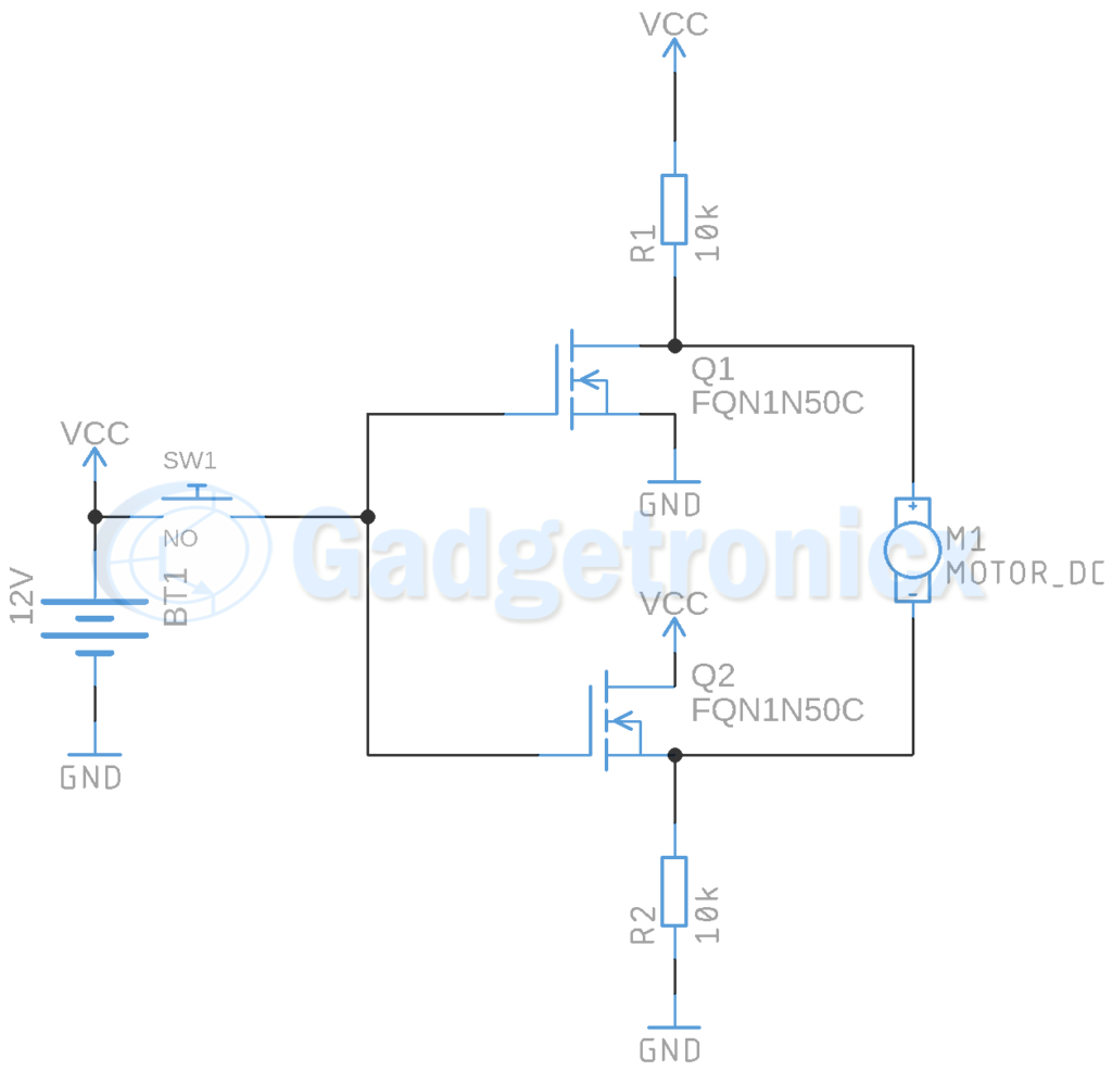
First we have our source of energy a 12VDC Battery. A Switch Sw1 connects it directly to the Gate of both the MOSFET. Source pin of both the MOSFET’s are connected to ground or negative terminal of the battery. When both source are connected to ground or negative terminal of the battery we will have the output for our DC motor in Q1’s drain pin and Q2’s source.
Connecting a button between the battery and each of the gates of FET can be used to control the ON/OFF state of transistor. When the button is not pressed the transistor will be in open state and the Motor receives 12V from the drain of the FET Q1 on its positive pin. And 0V from Q2 to motor’s negative pin. But when we press the button we put the transistors in saturation state. So the motor now receive 0V from Q1 and 12V from Q2, therefore changing the direction of motor’s rotation.
You can add motors in similar manner to control it altogether. To do this you should make sure your MOSFET is capable of handling the current intake of motors used here. Also in case if you are powering the circuit using a battery you should have in mind that the current intake of motor should be less than current draw capacity of the battery.
Leave your queries and feedback about this circuit in the below comments section. We will be happy to answer your questions 🙂
This circuit doesn’t make any sense. The current that goes through the motor always has to go through one of the 10kohm resistors, so the current can’t be greater than 1.2 mA which is way too low to drive a motor.


This circuit has to be an April fool’s joke. Drive a motor via 10k resistors!!! wow.
This circuit doesn’t make any sense. The current that goes through the motor always has to go through one of the 10kohm resistors, so the current can’t be greater than 1.2 mA which is way too low to drive a motor.
Can you explain how the FET are converting DC voltage into sine form for running the motor ?
Just curious why the 10K resistors are required. I plan on driving a motor rated at 2Amps. What wattage rating would these resistors need to be?