Code lockers are used for security purposes and it is of many types based on their complexity and level of security they provide. Here we are going to see building of simple code locker circuit using decade counter IC CD4017. It only requires minimal components and easy to build. It is capable of providing good level of security for the user.
CD4017:
This is a decade counter IC where the IC gives decimal coded output with each incoming pulse of the clock signal fed to it. The IC starts counting from Q0, Q1 to Q9 also this IC allows user to count the carry using the Carry out CO 12th pin. High Signal in the MR 15 pin will reset the count and starts the counting again from Q0. See the detailed working of CD4017 here.
WORKING OF CODE LOCKER CIRCUIT:
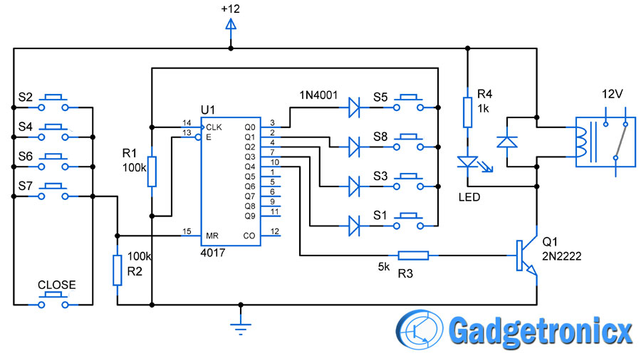
Here in this circuit we are going to use Q0, Q1, Q2, Q3, Q4 and MR pins for our code locker application. Switches S1,S2 to S7 will be used to feed the password input whereas Close switch is meant to deactivate the locker after usage. As stated already that with successive clock pulses fed to the CLK pin the IC starts counting from 0 to 9 via Q0 to Q9. Here the Switches S5,S8,S3 and S1 is the correct password sequence for this locker. These switches are wired in such a way to provide successive clock pulses to the CLK pin of the IC.
When a user presses S5 first it feeds a clock pulse to 14th pin which makes the IC to increment the count. This in turn gives high output at Q1 (2nd pin). At this instant when S8 is pressed it feeds the next pulse to CLK pin and then the output goes high in Q2 (4th pin). Thus pressing the correct sequence S5,S8,S3,S1 will move the output from Q0,Q1,Q2,Q3 and finally reaches Q4 where the transistor switch is connected. High in Q4 will activate the transistor which in turn the relay and locker ON.
Pressing switches other than the correct sequence that is S2,S4,S6 and S7 will trigger a reset to CD4017. Also wrong sequence of S5,S8,S3 and S1 will not create any response from the circuit. A close switch which also triggers a reset was used to close the locker after usage. An LED was added to indicate activation/deactivation of the locker.

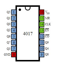 This is a decade counter IC where the IC gives decimal coded output with each incoming pulse of the clock signal fed to it. The IC starts counting from Q0, Q1 to Q9 also this IC allows user to count the carry using the Carry out CO 12th pin. High Signal in the MR 15 pin will reset the count and starts the counting again from Q0. See the detailed working of CD4017 here.


Congratulations, good job and clever design.
is it working
Yes