
 This electronic circuit is one of the simplest code lock circuit one can make easily in their home.This circuit uses one transistor a relay and a few passive components in it.The logic of this circuit is also very simple.Even this circuit is simple it works really fine and efficient for a simple cupboard or shelf lockers.
WORKING OF CODE LOCK CIRCUIT:
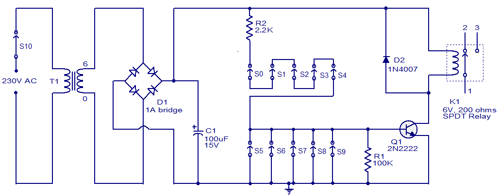
The working of this circuit is very simple it just uses a transistor as a switch with a relay at its collector as load.Five switches (S0 to S4) is arranged in series with a current limiting resistor R2 is connected across it.Another five switches (S5 to S9) is connected across the base of the transistor and the ground.So this circuit uses transistor as a switch and the transistor will ON only when all the switches from S0 to S4 was in ON state and S5 to S9 was in OFF state.This was the primary logic for this circuit.Lets see how to design it as per our wish.
Now coming to the design of this circuit we should shuffle arrange the switches in the panel in such a way so that the password will be too tough to guess.For example if your password is 58901 you should arrange it in the circuit that the keypad 5 will be your switch S0 then 8 as S1,9 as S2,0 as S3 and 1 as S4.Since it was in series the voltage will not pass through unless you pressed the keys in right combination.
Thus if correct combination of the key was pressed the transistor will be switched ON and it activates the relay circuit thus it opens the lock.If even on key from S5 to S9 was pressed then there will be no voltage to transistor thus making it to remain in OFF state.The device used to controlled using lock circuit can be connected through the relay terminals.The transformer T1,bridge D1 and capacitor C2 forms the power supply of the circuit.And diode D2 is a freewheeling diode which was used with relay circuit.
This circuit can be made of low cost and works very efficiently.We can secure our personal things in our shelf,cupboards etc using this circuit.Try it out and make yourselves feel secured.
UPDATE:
The above Circuit diagram have a small bug, the resistor R1 should not be pulled down to ground. It should be connected in such a way to connect the switch S9 and base of the transistor Q1 in order to bias it for switching the relay ON.


No i believe you are referring to push button switch. You cannot use it here and the switch given in the circuit diagram is SPST. The important thing in this circuit is to establish the path for current flow to switch the transistor ON. I hope now you understand its operation!!!
can u show me the bread board connected circuit pls.
i tried it out but the led that i connected across the relay isnt lighting up!
moreover, the switches i used are microprocessor switches! how do they work ?
r u supposed to keep them pressed until u get the output or what?
A brilliant idea! I’m contemplating installing one at our sheet iron gate, where it is housed, instead of a heavy-duty lock — everybody seems to have a key.
SCART Cables
Good…..
So complicated!
Not much…