Being a workaholic might sound kinda cool. But study says people who tend to work long hours sitting before computers have high risk of developing diseases like diabetes, heart ailments and so on. So I thought to design a simple circuit that can help with fighting the habit of spending long unhealthy hours sitting before computers. This circuit can help to alert you when it’s time to take a break from your work.
Taking five mins of break between 30 minutes of your work time can greatly improve your health. You should plugin this circuit into your computer when you begin to work and press a button. This will initiate the timing count and at the end of assigned time alarm will sound indicating the time for your break.
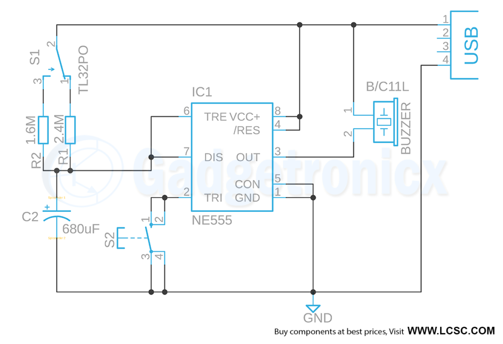
WORKING OF ALARM CIRCUIT:
555 IC is the heart of this circuit. It’s wired as monostable multivibrator where negative pulse in the trigger pin will push the output to high state. The timing of this high output is decided by the Resistor and Capacitor connected to connected to pins 6 and 7 of IC 555. So when a low pulse signal is fed into pin 2, the output will be high state and it will remain in high state until a fixed time decided by R1 or R2 and C2 values. The timing is given by the formula
T = 1.1 x R x C
Resistor R1 will yield T = 1.1 x 1.6M x 680uF = 20 minutes
Resistor R2 will yield T = 1.1 x 2.4M x 680uF = 30 minutes
The above circuit is powered from USB port of your computer. The SPDT switch S1 used to select the resistor which affects the timing of the alarm. The Switch S2 is used to apply negative pulse to Trigger pin. At this instant when the resistor R1 is selected, it connect with the Capacitor C2 which gives about 20 mins of high state output from pin 3 of IC 555. The output buzzer will be inactive when the output is in high state. Look at the way Buzzer is connected, it will be activated when pin 3 gives low state.
Once 20 minutes is elapsed the output will go back to low state. The buzzer will start to sound now indicating the time for a short break. If Resistor R2 is selected the delay of this high to low output transition will take about 30 minutes making our circuit to sound alarm after 30 minutes of your work time.
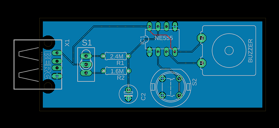
PCB DESIGN:
The PCB board was designed to directly connect with USB ports on your computer. Take a look at the parts list in the circuit diagram to buy matching parts to use with this board. You can download the gerber files for above PCB design below.
Sorry, but this circuit has never been tested! Pin 5 does not go to GND, leave it open or put a capacitor to it. To make it work with a long USB cable, it needs a power stabilization and or a resistor in series with the buzzer.

 The PCB board was designed to directly connect with USB ports on your computer. Take a look at the parts list in the circuit diagram to buy matching parts to use with this board. You can download the gerber files for above PCB design below.


Sorry, but this circuit has never been tested! Pin 5 does not go to GND, leave it open or put a capacitor to it. To make it work with a long USB cable, it needs a power stabilization and or a resistor in series with the buzzer.