Identifying unknown voltage is something we often come across when working with circuits. Of course Multimeter is the perfect tool for this application. But recently I came across a situation where my Multimeter turned out to be faulty and I was left with nothing to measure voltage from a circuit. Owing to the lockdown due to COVID-19 I was left with no option rather make a circuit that detects range at which input voltage stands. This circuit is a good alternative to identify four different voltage which ranges up to 12v. These voltage ranges are indicated by LEDs of different colors.
0 – 3.3v : White LED
3.3v – 5v : Blue LED
5v – 9v : Green LED
9v – 12v : Red LED
Working of Voltage range detector circuit:
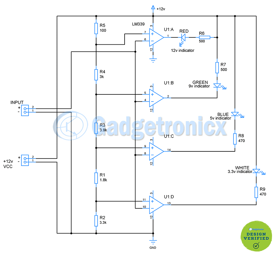
This circuit works based on comparators property of comparing two input voltage at its inverting and non inverting terminal. If voltage to inverting input exceeds non inverting input output will be low and vice versa. This circuit uses LM339 chip which is a quad comparator chip which fits perfectly for our purpose. 12v external power supply powers this circuit. Also, in addition to powering this circuit, it provides reference voltage to the non inverting terminal of comparator chips for comparison. Input terminal is used to feed the voltage that need to be probed or identified. This input voltage goes to inverting terminal of comparators.
Voltage reference:
The idea here is to setup different reference voltage to feed each comparators and compare them against the input voltage. This circuit can detect up to 12v. If you look at the voltage divider setup built using R1, R2, R3, R4, R5 you can observe each comparator is fed with different reference voltage. Consider U1:D from the above as an example here to calculate the voltage output from the voltage divider R1, R3, R4, R5 should be considered as series and should be added together. So the voltage divider takes the form
This 3.2v goes to non inverting terminal of U1:D chip. When the input voltage fed to inverting terminal exceeds this voltage 3.2v, output of comparator goes low and White LED connected in the output lights up. This indicates the input voltage is 3.3v and above. Likewise for U1:C chip reference voltage R3, R4 and R5 resistance in series and so does R1 & R2. So to determine voltage reference for U1:C chip the voltage divider equation takes the form
So when the input voltage exceeds or equals to 5v Blue LED lights up. This indicates the input voltage is equal to 5v or greater than 5v. In this instant White LED ( indicator for 3.3v) will be ON as well. Likewise the reference voltage for U1:B and U1:A is 8.9v and 11.9v.. So when the input voltage reaches 9v Green LED lights up indicating the input voltage range is 9v and above. Similarly when the input voltage reaches 12v Red LED lights up indicating the input voltage range is 12v and above. This is the maximum voltage range this circuit can detect. For 12v input voltage all the LEDs will light up along with Red indicating all the input ranges has been exceeded. Resistor R6, R7, R8 and R9 serves as current limiting resistor for LEDs.
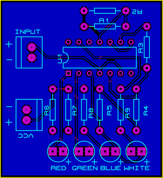
PCB design:
The below PCB design is of two layers with no vias. It can be built right at home using this method. I have added the pdf file that you can use with your printer to get the PCB traces. Also added the Gerber files if you want to get it manufactured using your production house.