Air horns are quite popular and been around for a long time now. Due to its nature of creating loud noise this is used in trucks, engines, vehicles and other locomotives to warn other vehicles and bystanders. Traditional air horns uses compressed air to make it sound louder. In this article we will see an Air horn that is built purely using electronics. This circuit uses oscillators using Schmitt triggers and speakers to achieve this Air horn effect. You can find more circuits in our Electronic circuits library page.
Working of Loud Air Horn circuit :
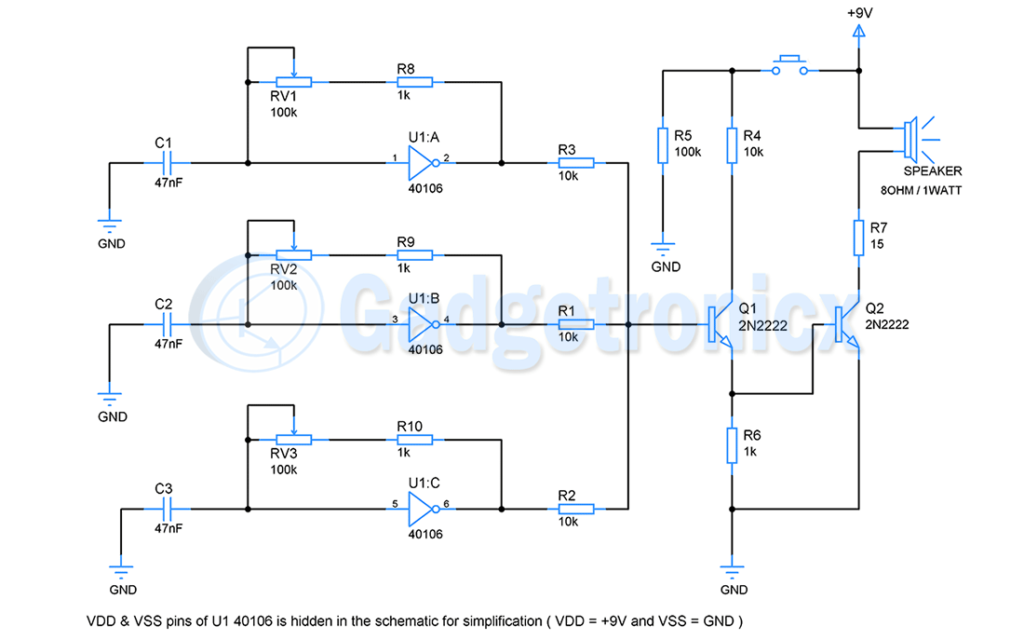
The circuit uses Schmitt trigger chip IC 40106 for building an oscillator. This schmitt trigger exhibit hysteresis. This hysteresis helps the schmitt trigger to achieve clean high to low and vice versa transition in oscillator output i.e square wave. Also this makes the oscillator less prone to noise in its input.
Oscillators:
There are total of three individual oscillators built around U1:A, U1:B, U1:C in this circuit. We will consider oscillator built around U1:A for the sake of explanation. When the circuit is powered ON we assume that voltage across all oscillator capacitors C1, C2, C3 will be zero. It means that there is no charge in the capacitor.
At this point the output of Schmitt trigger U1:A, U1:B, U1:C will be high. Though the C1, C2, C3 capacitors is of equal value, its very unlikely they will charge at same rate or they would possess equal charge when the circuit is powered ON.
For 1st oscillator built around U1:A, When capacitor starts charging using a feedback resistor from output to input of U1:A. As a result voltage across the capacitor starts increasing, so does the input voltage to schmitt trigger. When the voltage at input of the schmitt trigger crosses the minmum positive threshold voltage of U1:A 40106, output goes LOW. Now the capacitor starts discharging through feedback resistor via feedback resistor RV1 and R8.
The voltage at the input of U1:A starts dropping due to discharge action. When capacitor voltage drops below minimum negative threshold voltage of U1 40106 the input goes low and output switches to high state. The above cycle repeats. The capacitor used here takes very little time to charge and discharge since it is of low value. Also by adjusting the POT RV8 we can control the rate at which the capacitor charge and discharge.
Other oscillators built around U1:B and U1:C operates in same way. But the output square wave from all the oscillators will be different and it needs to be that way. The three square wave of these three oscillators combined using resistors R1, R2, R3. This signal is fed as input to the transistor Q1.
Emitter follower Amplifier:
The transistors Q1 and Q2 are configured to work as emitter follower. The signal at the base of the first transistor is exhibited at its emitter. This signal is further fed to the base of the second transistor. This boosted signal from these three oscillators drives the speaker.
The mix of these square waves will be of high frequency and therefore capable of creating fast oscillations in the diaphragm of the speaker. As a result we will obtain a loud sound Air horn. The push button is used here to activate the air horn sound. Until the button is pressed, the collector of Q1 is pulled low using resistor R5 therefore ceasing it to work as emitter follower amplifier. When button is pressed Q1 and Q2 operates as emitter follower creating the horn sound till the button is released.
Components required:
Speaker
Schmitt trigger IC 40106 – 1
Transistor -2 (2N2222)
Resistor – 1K, 10K ( 2 ), 100K, 100, 15
Capacitor – 47nF
Potentiometer – 100K ( 3 )
Push button
9V power supply
Hope this circuit is useful to you. If you have queries, suggestions and feedback leave them in the comments section below. Check out other alarm circuits in our website.


Hello,
Is an 80 Ohm Speaker available for this project and could it be a PA Horn to further enhance the loudness because I really need it to be loud.
Could this be operated on the 12 volt car system without damage to the Components?
Thank You I Love this Project,Do you sell it in Kit form?