Metal detectors are gadgets that is capable of detecting metal elements on a surface. The proximity at which the detectors can detect metals depends on the detector’s range it can cover. Here in this Metal detector circuit we are using a timer IC 555 and Inductor to detect metals and alert the user by means of an alarm from simple buzzer.
Part List:
NE555
2x 2.2uF Capacitors
10mH Coil Inductor
Battery 9V
Working of Metal Detector Circuit:
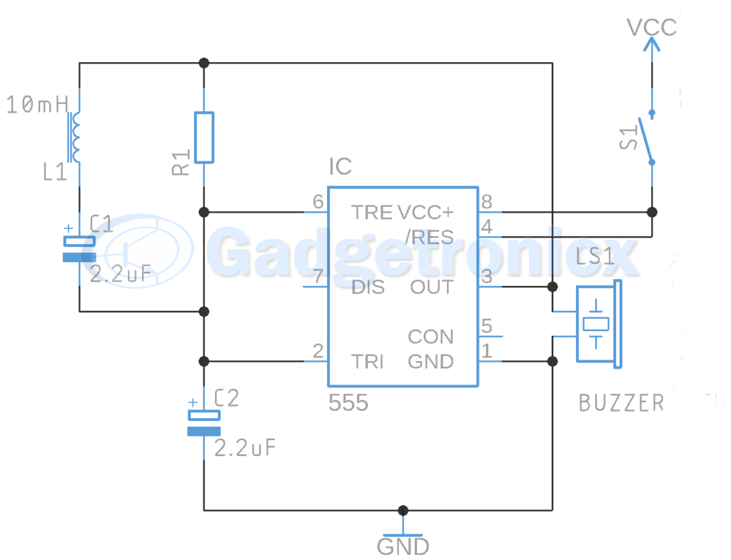
The 555 IC is wired as a Mono stable multivibrator. Monostable multivibrator is characterized by giving high output when there is low pulse signal to the input trigger pin. The duty cycle of output pulse from IC 555 is proportional to the Inductor L1 and Capacitor C1 which is connected in series to the trigger pin of IC 555. Here the inductor we use is an Air core. When current flows through the Inductor a magnetic field in proportional to the current flow develops around it. This magnetic field senses when a metal is brought near the inductor it’s inductance increases. This results in increase in flow of current and Capacitor starts charging quickly. Feeding the trigger pin of IC 555.
This change in inductance results in change in duty cycle of output pulse that goes to the buzzer. We can observe the change in the tone of buzzer. This change in tone of buzzer indicates the presence of metal before the detector. A switch S1 was added in the circuit to turn it ON and OFF when necessary.
Note:
Only air core Inductor should be used.
555 IC can source only max current of 200mA so make sure your buzzer current consumption don’t exceed that.
You can add speaker when you use transistor to act like a switch to operate the buzzer.
Increasing the inductance value increases the range it can detect the metals in the surface.


Thank you so much from Turkey. You have saved 3 students’ lives. We love you Mr. Frank
Thanks , what is it range ? And how to increase the range such as 2 metes please ?
Why are we using 2 capacitor in lcr circuit
The Capacitor connected to trigger charges changing the duty cycle of the output.
¿What is the resistance value?
You can use a resistor value of 1K.