
Tesla coils are probably coolest experimental circuit we could ever build. Tesla coils varies with complexity in its design and building. Here we have designed a simplest form of this Tesla coil circuit. This DIY circuit uses simple elements like a battery, a transistor, some resistor and your own Inductors that you can find lying around in your component inventory to create a Tesla coil and transmit energy Wirelessly.
COMPONENTS REQUIRED:
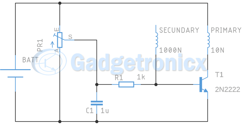
- Capacitor – 1uF
- Resistor – 1kOhm
- Potentiometer – 10kOhm
- Transistor NPN (can be 2N2222)
- Battery from 5 to 25V DC
- 10 spires Coil
- 1000 spires Coil
WORKING OF TESLA COIL CIRCUIT:
The secret of wireless energy lies in breaking the dielectric of the air. This is achieved two variable Voltages of varying intensity and distance. If we figure how to get a High voltage we can transmit energy through the air we get a Tesla coil. This is what this circuit exactly does. We have a battery of low voltage connected to a side of an Inductor (transformer). Also the important thing is that this side must be of low inductance means they should lower spires. This is going to connect to the collector pin of transistor.
We intend to create a voltage elevation which can be made by switching the voltage of one side of the transformer from low to maximum voltage. And then on the secondary side of Transformer a higher voltage is generated as the voltage is switching in the primary side. To control this we connect a capacitor C1 and a Potentiometer PR1 to adjust the frequency that is going to be switch the transistor. This is how we can generate high voltage. This breaks the dielectric of the air and allows a wireless form of transmitting energy. This creates tiny sparks around these coils resembling a Tesla coil.
NOTE:
- The relation between spires in the coil is very important, this need to be a high relation at least 1/100
Hope this Tesla coil circuit will be a super fun build for you. Please leave your questions and feedback in the comments section below.


Hello dear friends
Thank you for your articles, you are the best
hey , my name is ishak and im student , i have some questions in theoretical, if you please could help me with that , so i was going to make the same circuit but without the capacitor ! so what i had understand , this circuit is an auto resonance cause of the transistor he can be passing and blocking like an interrupter , so i can calculate the resonance frequency of secondary than my transistor will play the game so both circuits primary and secondary will get the same frequency and this is oscillation , now when you add capacitor i can understand that this C will help the transistor to get to right frequency at the right moment just like a swing.
am i right that this is the real role of the capacitor just helping ? and whats the formula for frequency in the primary i have feelings its not f=1/2*pi*sqrt(L*C)!
i have another question about the current ,we know that the secondary coil is in the vacuum witch causes a higher current in the primary ! do u have any idea could help about how to calculate the current in the primary ?
and thank you so much any way ill do your circuit because i have already made 1000N in the seconday !