
Infrared sensors have wide variety of applications ranging from robotics and automation. IR sensors have been doing quite a great job in all these applications for many decades. This article teaches you to build a simple Infrared sensor module circuit which can be used with any application which needs detection or sensing.
INFRARED SENSOR MODULE CIRCUIT DESIGN:
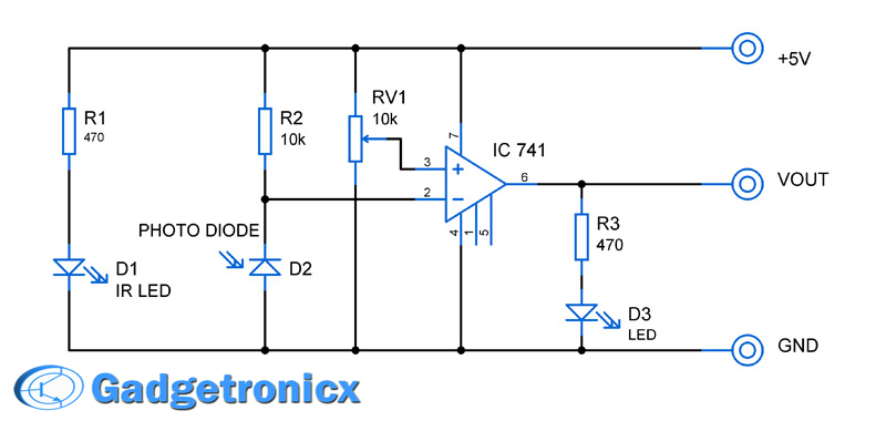
WORKING:
A simple IR led and Photodiode used for emitting and sensing the IR beam. And Op Amp IC 741 is used as an comparator which in turn switches the output level as either logic 1 or logic 0. The Variable resistor RV1 used to tune the sensitivity of the detector by altering the reference voltage to the comparator. And at last LED D3 was meant as an indicator in case a IR beam is detected or reflected.
When the circuit is powered IR LED D1 emits Infra red beam. The photodiode D2 was connected in a reverse biased manner along with a resistor R2 in series. When there is no IR beam incident in the photodiode no current passes through it which in turn leads to no drop in voltage and inverting terminal of the Op Amp is fed with max voltage that is 5V. Since the voltage in the inverting terminal is more than the reference voltage at the “+” terminal of op amp the output stays LOW or logic 0.
When IR beam is reflected by any body which makes the beam to incident on Photo diode, current passes through it and in turn a drop of voltage occurs between the terminals. Now the reference voltage at the + terminal of Op amp is more than the – terminal. The output of Op amp switches to high or Logic 1 state.
This module will be highly useful to interface with Microcontroller for sensing since it provides the output in two logic levels which is compatible many microcontrollers.
INFRARED MODULE:
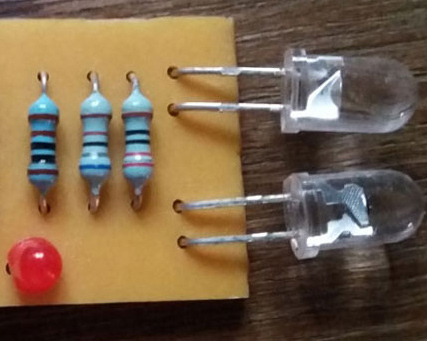
IR LED and Photodiode must be placed as shown above
NOTE:
- You can adjust the sensitivity of the module by altering the resistance value of the POT RV1.
- Omitting the Comparator part and RV1 will give you a pure analog signal through which incident light intensity can be measured.


Have been working on rehabilitating a console which has a coin drop master start circuit. This console is more than 30 years old. It has been subjected to abuse. On the underside of the mlum plate, there’s two sets of ‘pitcher catcher devices. The only identifying marks on them is KT3010 Mexico 8423. I researched the ID #, but nothing results. It’s obvious that 8423 is a date of manufacture.
Each device has two leads from the epoxy, and both are semi-translucent (amber) colour. On one side of the slot, the two devices are wired in series. A red wire attached to one lead, the other lead goes to the 2nd device, and the 2nd lead on that device is a blk wire. So, it’s obvious that these are the power supply rails (15vDC). On the other side of the slot, a red wire attaches to one of the device leads, then a yellow wire attached to the 2nd lead, and then goes to the 1st lead of the 2nd device. Attached to the 2nd lead of the 2nd device is a yellow wire that goes to the main timing board. The main timer is a NE555 (actually made by SIGNETICS, with an ’84 date code). The output of this master timer goes to a second board (actually a cluster of them), which has a dual ‘555’ (NE 556) timer. When this board is signaled, it sends out short bursts to make a small incandescent lamp flicker.
Since I cannot find any documentation for the ‘devices’ described above, I matched up pairs of IR LED (940 nm) & IR photo transistors. Using the original p.c. boards I cannot get the circuit to work the way it was originally intended to. I believe that the original coin detector circuit was created by sawing in half a typical IR detector pair, as you would find in a rotary counter circuit, where a perforated wheel is attached to the shaft, counting the revolutions. It seems that the circuit is designed so that the IR LED (emitters) are wired across the power supply rails, and on the other side of the coin slot, the two phototransistor (receivers) are wired in series … the collector of the first one is connected to the + V, the emitter goes to the collector of the 2nd transistor & the emitter goes to the input of the master ‘555’. When there is no coin drop, the transistors are biased on, sending a +v tp pin2 of the 555. When the beam is broken, the Trigger input (pin 2) is set, and the timer starts.
I know this is long winded, but I’d appreciate any thoughts that you have regarding this circuit, especially at the coin drop end, since this is where the problem continues to lie.
I build and this is not working , lost few hours and my good circuit already built.
This circuit was copied from one using an LM358 opamp. that one works. this one cannot work with a 741 opamp. The part will not run well on a single 5 v supply, and neither the input nor output operating voltage ranges support the components shown.
Why not then give a link to the correct circuit. When you leave it hanging, you’re just hating.
This is working for me as the LED indicator does in fact light up when an obstacle is detected, however, the LED remains dimly lit at all times when there is no obstacle – even in complete darkness. It’s like there’s some voltage bleed-through. Any ideas?
Hi Scott, The circuit is designed that way once the power supply is ON LED will turn ON emitting IR beam all the time its just when obstacle passes through IR beam is reflected back to diode activating the output. Hope it helps.
If you don’t mind kindly share the picture of Sensor you have built using this design. You can mail this to webmaster@gadgetronicx.com
It’s fake not working.
It’s tested. Kindly try it again.
I think when Jason asked “What was it’s purpose in the original module?”, he referred on the transistor. I am also curious regarding that, but hopefully the circuit works with or without it as well.
Got what you mean to ask. You don’t need to worry about transistor. I have basically included the image for demonstration. Will update the article to avoid further confusion.
i am a little confused..!!!!
what is the working principle here???
the IR diode(D1) emits IR radiation and the photo diode(D2) picks it up right??
but in the actual circuit board they are side by side so ,then won’t the photo diode pick up IR radiation directly from the IR diode?????
I know your question is over 2 years old, but I ran across this nonetheless… LED’s are “unidirectional” – sort of! The fronts are lensed and focus the beam straight ahead and the phototransistor is only looking forward as well, there’s very little “peripheral vision” involved!
easy understanding and compact design. i am new to this feild. wherther any body got the out put from this.
Sorry i was new in electronics, but can you help me ? what is the name of the blue component is located under ic on the picture.
Thanks Before
Andhika,
It’s a variable resistor.
On the picture there appears to be a Transistor but on the schematics it is not shown? Also no mention of it in the workings.
It’s the picture of module i had, i felt it was not really necessary when you want to make one. So omitted in the schematic design.
Ah thanks for that information as I thought i was going mad for a minute.
Nice neat module.
Sorry, i should have mentioned it in the article my bad.
What was it’s purpose in the original module?
Jason,
It’s an IR module it’s main purpose is obstacle detection