
After COVID-19 we have come up with many ways to disinfect our hands, different surfaces in our homes and so on. This circuit is version two of Solar powered UV lamp project where it uses 5 UV-C LEDs which was published earlier in our website. The intensity of germicidal light produced using five LED’s will be less and moreover the range of disinfection will be short. To improvise that 20 UV-C LEDs are added in this germicidal UV lamp design powered using a Lithium ion battery with battery discharge prevention unit.
UV-C LEDs:
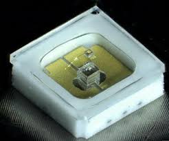
This design uses a special UV-C LED which is capable of producing UV light which falls in germicidal wavelength. This ranges from 265nm and 280nm. This LED generates UV light of 275nm in wavelength. Also this LED maximum current is rated at 50mA at 5.2V.
WORKING OF GERMICIDAL UV LAMP CIRCUIT:
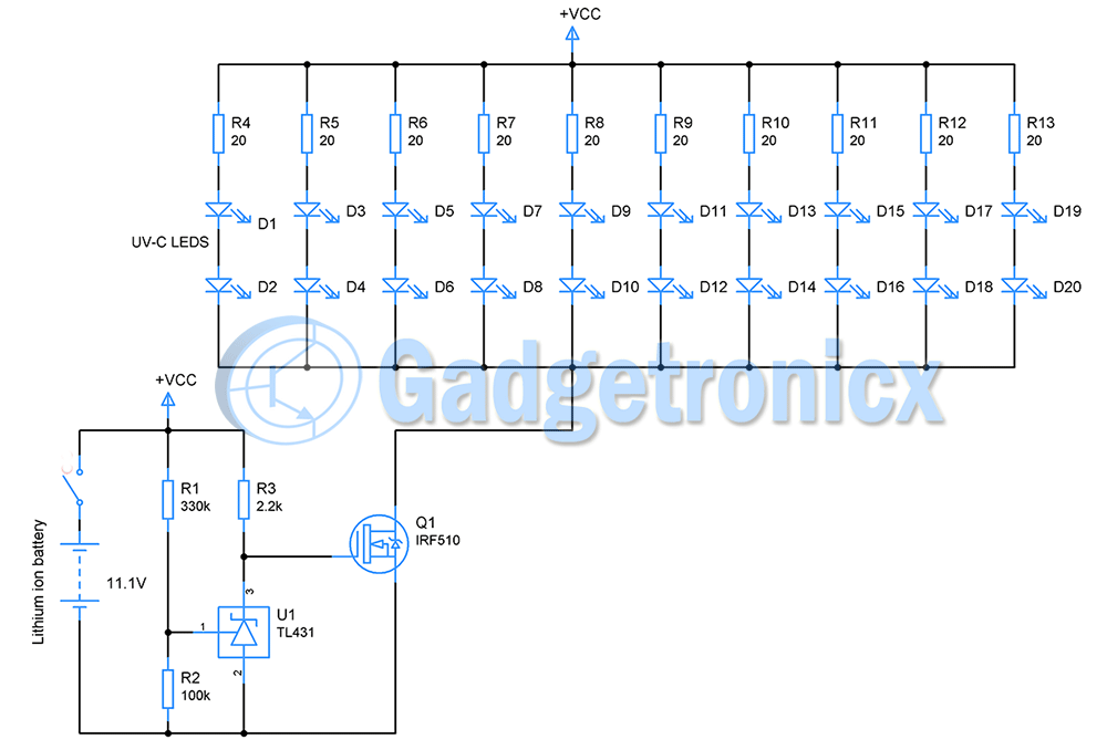
Figure 1: Lithium ion battery powered UV lamp circuit
LITHIUM ION BATTERY:
Let’s start looking at the battery used in the circuit. It is a 3 cell Lithium ion battery pack with nominal voltage of about 11.1V ( 3.7V per cell ) and 2200mAH current capacity. Discharge curve of a Lithium ion battery indicates when battery is fully charged, voltage across its cell will be 3.9V.
However when battery capacity is discharged up to 80% of its total capacity then voltage across it will drop to 3.6V per cell. This is 10.8V for 3 cells. This is the voltage at which we need to stop LEDs from drawing current from the battery. Current draw beyond this point will damage the battery’s life.
BATTERY DISCHARGE PROTECTION:
For this purpose TL431 is used. This is an adjustable voltage shunt regulator. It pretty much acts like a Zener diode. But unlike Zener diode its regulation voltage can be adjusted by varying voltage input to its 1st pin ADJ. According to its datasheet TL431 is capable of regulating voltage from 2.25V to 36V.
Here our regulation voltage is going to be the cut off voltage 10.8V. When voltage across the battery drops below this, TL431 should stop its regulation and voltage in its 3rd pin will drop to zero. As I said earlier voltage to 2nd pin will decide the cut off voltage so a voltage divider using resistors R1 and R2 is used for this purpose. The regulation output voltage is given by this formula according to its datasheet.
Vo = (1 + R1 / R2 ) Vref
Vref is the reference voltage which is wired up internally and equals to 2.5V. For an output voltage of 10.8V, let’s fix R2 as 100K
10.8V = ( (100k + R1 )/100k ) x 2.5V
1080k = 250k + 2.5R1
R1 = 332k
Choosing the nearest standard value R1= 330k
The cut off voltage is now set to 10.8V. In order for TL431 to regulate correctly it requires a minimum current of 1mA to 100mA. R3 here limits the current flow to maximum of 5.3mA when battery voltage is maximum. This current flow will keep the voltage across its pin 3 stable to 10.8V.
LED AND MOSFET DRIVER:
20 UV-C LEDs are connected in two series and ten parallel configuration. Each pair of LED’s consume maximum of about 50mA current. That gives about 500mA for 10 pairs. TL431 can only fix reference voltage but cannot source or drive such large current. Therefore a N-channel MOSFET IRF510 is to used to drive the 20 LEDs. The maximum drain current of this MOSFET is 5A therefore it will be a good choice. You may need to add a heat sink to prevent it from heating up.
A resistor of 20 ohms is connected in series with LED pairs to limit the current flow.
SUMMARY:
When voltage from battery is maximum – 11.7V, battery will be in full charge state. TL431 will regulate the voltage down to 10.8V to drive the gate of MOSFET. This will turn the LED’s ON.
As battery capacity depletes and reaches 20% ( 80% consumed ) voltage will drop below our cut off voltage 10.8V and voltage across TL431 drops as well. Gate of MOSFET will now be low and therefore LEDs turn off. Thus the discharge protection prevents the battery from over usage.
RUN TIME:
The typical current draw of this circuit is 510mA ( LEDs, MOSFET and TL431 ). It is safe to discharge up to 80% of battery’s total capacity per charge cycle. This is 1760mAH for a 2200mAH battery.
Run time = 1760mAH / 510mA
= 3.45 hours
This battery can run this germicidal UV lamp circuit safely for 3.5 hours.
WORKING EXPLANATION IN A VIDEO:
NOTE:
- Lithium ion batteries are quite tricky in nature to charge and therefore recommended to buy a matching charger to your battery
- This circuit can be tailored to other battery types and cut off voltages. Look for discharge curve of battery you choose and recommended discharge capacity to determine the cut off voltage. Use the above mentioned calculation to fix your cut off voltage.
Check out other circuits in our Electronics circuits library. If you have any queries and feedback leave them in the comments section below.


Hi Frank,
If you look at the circuit, you will notice thatvoltage divider R1, R2 form a 430K continuous leakage path that would fully discharge the battery. Worse is that the TL431 is used as a shunt regulator. When the voltage goes below the reference value, the TL431 turns ON and now the battery is further discharged through R3. If the battery cutout is 10.8 volts, the 10.8 / 2,200 = 4.9 ma of current that will discharge the battery. There is a much better circuit to protect the battery from discharge. Let me know if you would like an article with the improved cut-off circuit.
The circuit will continue to conduct current after the LED’s are turned OFF. This will damage the battery. What is needed is circuit which needs to be activated with a push-button and turns OFF completely when the battery voltage drops below a specified level. I have designed such circuits that work in that manner. This design needs an improved update.
Good day Ron,
TL431 is used to cut off the battery once voltage across battery reaches 10.8V . At this point the MOSFET will be forced to stop acting as a switch for UV-C LEDs. This should turn off the UV LEDs and stop current draw. Also there is a SPST switch to turn the whole circuit ON and OFF.
I cannot see what am missing here, can you kindly point out what improvement can be made here.
Hi Frank,
When the TL431 turns ON (shunt regulator), Q1 turns OFF. However, the battery continues to discharge at a rate of 10.8 / (2.2K // 430K) = 10.8 / 2188 = .00493 A or about 5ma. If left for a long period of time and having forgotten to turn the unit OFF, the battery will discharge to 0. This could result in damage to the battery.
There is a two transistor circuit that does the same thing only the leakage current of the transistor (nano amps) is passed. Essentially zero. If you would like the circuit as a new article, I can send it. Regards, Ron.
Hi Ron,
I see what you mean 5mA indeed will discharge the battery’s juice. Increasing the 2.2K resistor will perhaps cut this down but still at least 1mA is necessary for TL431 to perform the regulation. I will update the design by substituting the 2.2k res with alternate one, at least it will reduce the current draw. Also I will add notes about this.
That sounds great Ron, would be great to have the transistor circuit.
Thanks,
Frank Donald