
LED based torches are quite extensively used these days. The important reason for using LED is because of their low power consumption and life. Here is a LED torch circuit which uses 3.7v Lithium polymer rechargeable battery. As a added feature this circuit also comes with battery discharge protection. This prevents the battery from over discharge which extends the battery performance and life.
LED TORCH WITH BATTERY PROTECTION CIRCUIT:
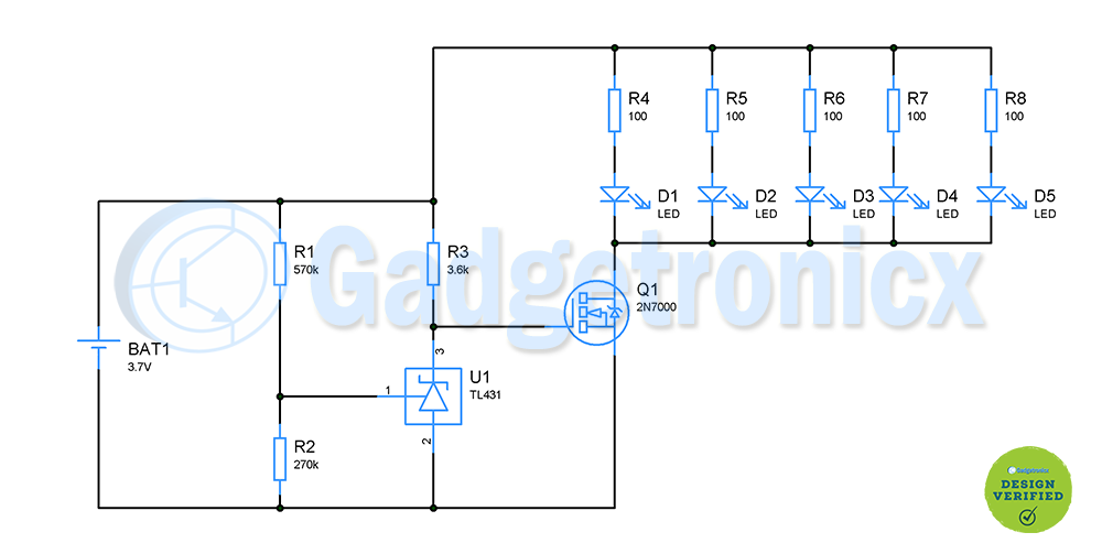
The circuit uses a 3.7v/1300 mAh Lithium polymer battery. When fully charged voltage across this battery will be about 4.2v. This circuit overall consumes maximum of about 110mA which is about 0.1C discharge rate. At this discharge rate cut off voltage of this battery will be around 3.6v where at this point battery would have lost 80% of its charge We need to stop the LEDs from drawing the current from batteries any further for better battery performance.
To protect the battery we are using a voltage shunt regulator TL431 for which we can adjust the output voltage from 1.25 to 36v. We need to stop the LED’s from drawing current once battery voltage reaches 3.6v, Therefore we need to set up the output voltage of TL431 to 3.6v as well. This voltage will be in Pin 3 of TL431. This can be done by feeding precise voltage input to it’s 1st pin. Therefore we are using a simple voltage divider setup of R1 and R2 for this purpose. This output voltage formula is
Vo = ( 1 + R1 / R2 ) x Vref
= (( 270k + 510k )/ 270k ) x 1.25
Vo = 3.6
Using our component values in the above given equation will result in 3.6v output voltage. Here Vref is internally wired inside the shunt regulator and hence equal to 1.25v. And as per the datasheet the minimum current Iref for regulation is 1mA. Setting the Vout to 3.6v of TL431 will drive the MOSFET gate pin. Voltage across a full charge battery will be around 4.2v. When battery is used more than 80% of its capacity, battery voltage will drop down to 3.5v output voltage of TL431 will be zero since battery voltage drops below it’s preset Vout voltage. Now Gate voltage of MOSFET will be zero hence it will move to OFF state.
MOSFET DRIVE:
N channel MOSFET 2N7000 will drive our LED’s. This MOSFET is capable of driving load up to 200mA. 5 LED’s are used with this MOSFET with each LED consuming about 20mA with overall load of 100mA connected to MOSFET drain. When TL431 voltage drops from 3.6v, Gate turns off and as a result LED goes off as well.
NOTE:
- The circuit overall consumes 110mA current, therefore this battery can power this circuit up to 10 hours before battery capacity drops below 80%.
- Choose your MOSFET appropriately to your load current.


the mosfet is always pulled up by the 3.6 resistor connected to positive, so when the ref. of 431 drops below 2.5 the mosfet will still be connecting. i tried it and just by re-placing the 3.6 kohm resistor to GND it will work well.
Reference voltage of the TL431 is 2.5V, not 1.25V – you even linked the datasheet. The 2n7000 seems like a bad choice from its R_DSon, output characteristics and thermal limits, there are far better logic level FETs available which will have lots of headroom available…
Hi Frank, sorry to comment on a different post but I was reading your other post ‘Random number generator circuit’ where you invite readers to comment ‘in the below comment box’ – but there is no comment box under that post! What’s the best way to send you my question about your random number generator circuit? Thanks in advance.
Hi Daniel,
Sorry about that. I have enabled the comment box in the Random number generator circuit page – https://www.gadgetronicx.com/led-torch-battery-protection/ . Please post your questions in this page as it will be useful for others who might have the same question.
I believe for under voltage protection it needs a P channel MOSFET in the positive supply rail with the gate connected to the same point as the diagram. The circuit as drawn would only provide over voltage protection.
It appears that battery discharge is “essentially” stopped by the circuit, as drawn, by shutting off the MOSFET “switch” that provides “ground” connection for the LEDs, if the input to the circuit (that is, the battery voltage) falls to 3.6 Volts. At that point, the only effective drain on the battery (in the “MOSFET off” condition) is the series combination of R1 and R2, which is 840 Kohms.
Although that does leave “some” drain on the battery, it is about 5 micro-amps ( @ 3.6 V.). You’d have to neglect your “torch”/flashlight quite a while for that tiny drain to do in your 3.7 V./1300 mAH Battery, even in the discharged state at 3.6 V. However, it is true that after a fairly long time of say weeks this could start to be a factor. I guess that (@3.6 V.) there would be the equivalent of 1 mAH drain every 200 hours or 8 days. So one may not want to leave this device untouched for years in a drawer and expect it to work.
The easiest remedy is to recharge your battery when under-voltage “shuts you down”. Seems like one should want to do that anyway.
Thanks to the author for the article!