Theft alarm circuits are quite famous and you probably could have seen plenty of different versions of it. The above circuit is yet another burglar alarm circuit but a simple one which would take only 5 to 10 mins of assemble and set up in your home.
WORKING OF THEFT ALARM CIRCUIT:
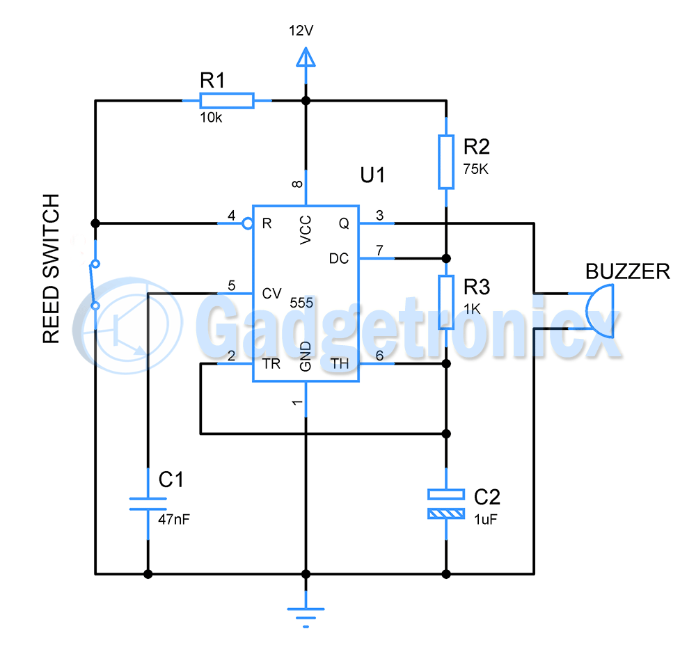
555 timer lies in the heart of this circuit. Here it is responsible for generating pulse to drive the buzzer. The 555 IC is wired as an astable multivibrator but with teeny tiny modification to make it work as a burglar alarm. Usually for astable multivibrator using 555 IC 4th pin ( reset ) is connected to Vcc but in here we have connected a reed switch to it. Reed switch is just like a normal switch but the difference is that reed switch gets closed only under the influence of a magnet and cannot be operated manually. When a magnet gets near a reed switch, it closes the connection and current flow occurs through it. But when magnet moves away it breaks the connection and current ceases to flow.
As you can observe in the above setup the reset pin is grounded in when the reed switch is closed ( magnet is near the switch ). This means that 555 timer will not produce any output pulse in the output. As a result buzzer will be turned off. But when the magnet is taken far from reed switch, the switch opens. This forces 4th pin ( reset ) to connect with Vcc. This in turn will completes the astable circuit and output pulse of steady frequency will be generated in the 3rd pin of 555 IC. This will be then fed to buzzer which acts as a sounding element or in words as an alarm.
The components in the above circuit where chosen to provide a output frequency of 18hz.
f = 0.693 x ( R2 + 2R3 ) x C2 = 0.693 x ( 75k + 2 x 1k ) x 1uF = 18hz. This is sufficient for us to drive the buzzer in the manner of an alarm.
So here is a illustration image showing how this burglar alarm should be setup in your home. Place the reed switch on the door frame and magnet right on the door. These must be placed in a way when the door is closed, the magnet should be able to influence the reed switch. This in turn will close the connection. Connect the reed switch to the circuit using long wires. Keep the circuit a bit high so that it will be out of reach for anyone who enters the house.
NOTE:
The setup of this circuit is very important for it to work effectively so make sure it is done correctly.
Switch this circuit on when you want to set up the alarm ( preferably night ) and turn it off when it is unncessary.
12V buzzers are quite capable of producing loud sound in my experience and only consumes less current. If you want your alarm to be more louder use a loud speaker with your circuit. But use a transistor to switch it ON and OFF, since 555 cannot supply enough current to drive a loudspeaker.
Hope this circuit was useful to you, do try this at home and let me know your thoughts and queries. Happy making 🙂