
RF Signal jammers are circuits used to jam RF signals of particular frequency. These circuits jam RF signals around us stopping the device from reception and decoding of these signals. These kind of jammers block signals from Cell Phones, Wireless Cameras and so on. This circuit we are about to see can jam signals ranging from frequency 2 to 2.5Ghz which is the operating frequency of Smart Phones.
Disclaimer: Using Jammers are illegal in many parts of the world, so use it with your own discretion.
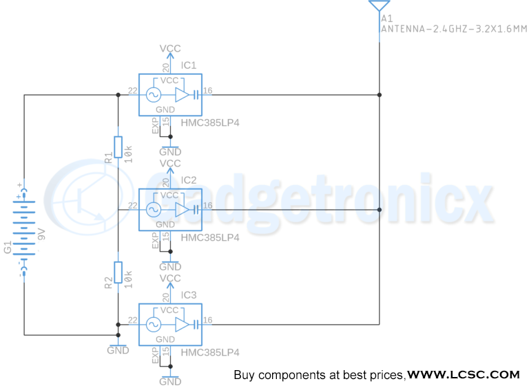
RF JAMMER CIRCUIT DIAGRAM:
COMPONENTS USED:
- 9V Battery – 1
- 3V Battery – 1
- RF ANTENNA – 1
- IC HMC385LP4 – 3
- 10k Ohm Resistor – 2
WORKING OF JAMMER CIRCUIT:
This circuit uses IC HMC385LP4 which has a built in VCO is capable of generating signals of frequency out from 2.1 Ghz to 2.5 Ghz. The signals generated from this chip is of 0.5Ghz bandwidth powerful signal. In addition to this HMC385LP4 has a built in Amplifier to boost the generated signals from VCO. The amplified signals AC coupled which removes low frequency noise and other DC elements in the signal.
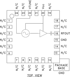
This IC should be supplied with 3v DC power supply. The input voltage in pin VTUNE determines the output signal frequency. So we have a simple voltage divider setup to feed the VTUNE pin with corresponding voltage to generate frequency of our desire. Check out the datasheet of IC HMC385 for more information.
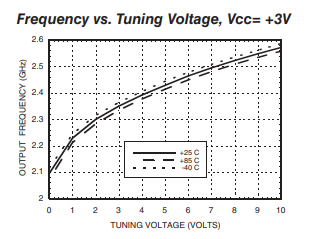
From the above graph you can observe the output signals of different frequency varies with the tuning voltage. In our jammer circuit 9v of tuning voltage goes to IC1, 4.5v to IC2 and finally 0v to IC3. Looking at the frequency values for the above tuning voltages we can see that Output frequency of IC1 will be of 2.5Ghz and IC2 will be of 2.3Ghz and IC3 will give 2.1Ghz frequency signal. The output signal from each of this IC will be of 4.5dBm which is quite strong signal.
Thus a combination of RF signals of frequency 2.1 GHz , 2.3Ghz, 2.5Ghz signal each with bandwidth of 0.5 GHz signal is radiated using the Antenna. Therefore this will override any other signal that has similar frequency. This will result in jamming of that particular frequency forcing the device to cease working.
NOTE:
You can use a potentiometer to modify the tuning voltage and alter the output frequency. But fixing the tuning voltages using voltage dividers offers more control to us so this method is used in our circuit.


 car at home")

very good
Where could we simulate the RF jammer circuit….any software or anything…let me kno