
Inverter is a gadget that is used to convert low voltage DC to AC high voltage. This circuit comes in different shapes and sizes also these circuits differ in Output load and waveform. Similarly we have designed a Square wave Inverter circuit that is capable of driving 220v device and handles 60 Watt load. This circuit is powered from a DC battery and turn it into AC voltage to power some loads such as lights and other AC elements within the limit of 60 Watts. The circuit is designed to be used with 12v Battery.
COMPONENTS REQUIRED:
- Battery 12VDC 5AH
- Capacitor – 0.22uF, 0.01uF
- Diodes 1N5400 – 4 (or other that can support at least 3A)
- Resistor 1kOhm – 1
- Resistor 4.7kOhm – 1
- NPN Transistor 2N3054 – 4(or other that can support at least 5A)
- NE555 Timer
- Transformer 12V to 220V 60W
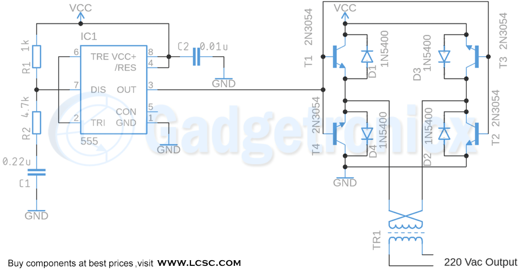
WORKING EXPLANATION OF SQUARE WAVE INVERTER CIRCUIT:
The working of this circuit starts with IC 555 which is wired as Astable Multivibrator. This Multivibrator is characterized by generating square wave pulse in the output at a fixed frequency. This is necessary to transform the DC Voltage or signal from the battery to AC voltage. The signal from this Multivibrator can Saturate and Open two pairs of transistor at a time.
These transistors will will act as switches. The output from 555 will have almost equal time in high state as well as low level state. The transistor will output +VDC to the transformer in half cycle of Square wave with T1 and T2 Saturated leaving T3 and T4 in open state. And for the other half cycle Transistors will output -VDC to the transformer since transistors are inverted. This will give us the AC signal we need. The Transformer we have used is a Step up one with Input voltage of 12v and output of about 220v AC.
When using a 12VDC 5Ah battery this circuit will give us 60W approximately to use for output load. This 12v Inveter circuit will consume less than 25mW. Therefore we can safely use approximately 260mA with the 220VAC output.


you circut don’t work, T3 and T4 won’t switch, you need 2 PNP to build a bridge
and a second signal
Confirmed, this circuit does not work.