 |
| Dual power Supply Circuit |
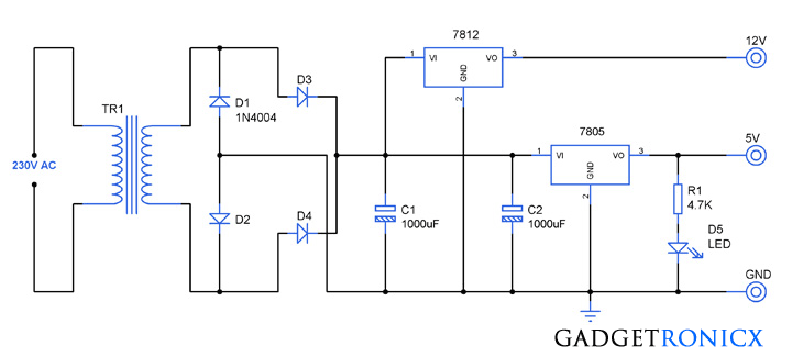
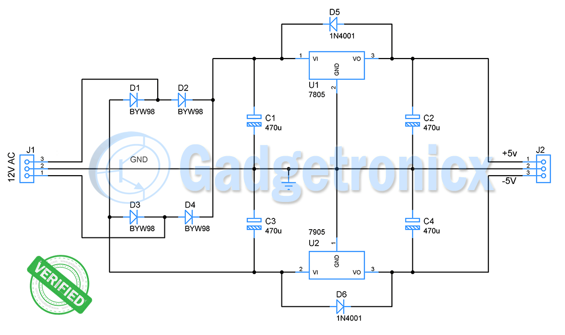
Power supply form the basic building block of any electronic circuits and therefore its important to familiarize the DC power supply circuit construction. The above given circuit illustrates a simple approach to construct a dual DC power supply of 5V and 12V from the 230V AC mains supply. The Voltage ranges 5V and 12V are widely used in all kinds of simple electronic circuits, so its meaningful to learn this simple construction.
WORKING OF DUAL POWER SUPPLY CIRCUIT:
The above circuit obtains power from a 230V AC mains supply voltage and fed into a step down transformer for transforming higher voltage supply to lower one. The transformer TR1 can be of 230V primary ,15V secondary and 1A step down transformer. The stepped down voltage can be fed into the bridge rectifier made of four 1N4004 diodes for the conversion of AC supply to DC one.
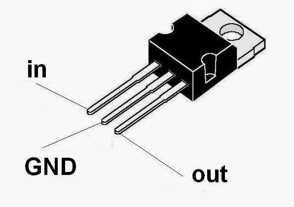 |
| IC regulator pinout |
The output from the bridge rectifier was filtered by the capacitor C1 and C2 to offer a steady DC level to the input pins of the regulators used in the above circuit. The DC voltage is then fed in to the IC 7805 which is a 5V regulator and also to the IC 7812 which was a 12V regulator. The output obtained from the 7805 & 7012 are 5V and 12V respectively. A LED D5 was connected through the current limiting resistor R1 for indicate the state of the device.
This kind of circuits are highly useful where two dual range of DC voltages are used to power the operation of a circuit. Varying the voltage regulator IC ‘s 7805 or 7812 with 7806 and 7808 to obtain 6V and 8V as output. But each IC have minimum and maximum voltage requirements, so make sure you build in such a way to meet the requirements.

could it be okey if i use 3 amp center tap transformer?
Jether,
Yes you can use 3A transformer, but you only will get 1A in the Output since 78XX IC capable of delivering 1A to the load.
anyway I sent see the recommended transformer for 15v project 1A
Pedro,
I couldn’t figure out the reason for transformer heating, also the transformer you are using didn’t fetch much information from the internet. The reason you have to use 15V transformer or higher is because the voltage regulator IC will drop some voltage while converting output to 12 and 5 voltage respectively. So try replacing your 12v with 15v transformer and see if it resolves the issue.
de qualquer maneira mandei vir o transformador recomendado para o projeto de 15v de 1A
Good afternoon the transformer that I used was 12V , I had asked before using the technique of the teachers if it was possible to use it with the specifications
k-CF48-002BR-U09 this is the model but can not find anything about it.
hello I’m having a little problem with the power supply design, I used a 12V transformer in the project, and it worked but began to heat a rectifying diode and the transformer became increasingly hot
Pedro,
Extreme heating up of Transformer and diode is unusual, there are number of things which might go wrong. See if you have given the connections right. By the way share the specs of the transformer you are using in your circuit
Need to build a pair of dual power supplies. 12V @ 4-5A and 5V @ 10-15A. 5V needs to be as quiet as possible. Are there any circuits like this around? Can I just modify the above circuit with higher power components and heat sinks?
Thx,
Joe B
can you mail me caculation part
Mahesh,
What calculation part you are referring to?
Hi Joe,
Sorry missed your comment. The IC 7805 and 7812 can only source 1A of current. Am afraid you cannot use this circuit.
Hi i have a a few question about C1 and C2, what is voltage for C1 and C2 1000uF for this dual power supply circuit?
Pedro Rocha,
The two capacitors C1 and C2 are rated 25V/1000uF in this circuit.
Hello.
I need the 5V output to power a 5v 3A device and the 12V output to an 1A device, is this power supply ok for that ?
Luis,
IC 7805 and 7812 is capable of sourcing 1A current only so it will fit your 12V,1A device requirement but for 5V ,3A device you might need a current amplifier.
This 12V & 5V Dual power supply Circuit is really so good for maintaining good electric supply and I’ve been using such dual power supply circuit and really its working well for me. Thanks
Glad to hear it….Feel free to browse our circuit collections
I was recommended this website by my cousin. I am not sure whether this post is written by him as
no one else know such detailed about my problem.
You’re wonderful! Thanks!