
I always get thrilled by gadgets used in Action and Science Fiction films and I ask myself how cool it will be if it’s real. To make this a reality I have designed a super simple yet effective FM based wireless spy microphone that will allow you to broadcast audio signal and let you spy on people within a certain range. The circuit uses FM frequencies to transmit audio signal produced by the MAX2606 IC. On the other hand any FM receiver such as a regular FM radio or even the FM radio app on your Smartphone allow you to spy in the room or place where you have planted your bug.
Warning : This circuit is for educational purposes only. Please check for the legality before attempting the project within your area. Because in many parts of the world interfering with certain FM Frequencies can be considered as a Criminal ACT. And we will not take responsibility for such consequences.
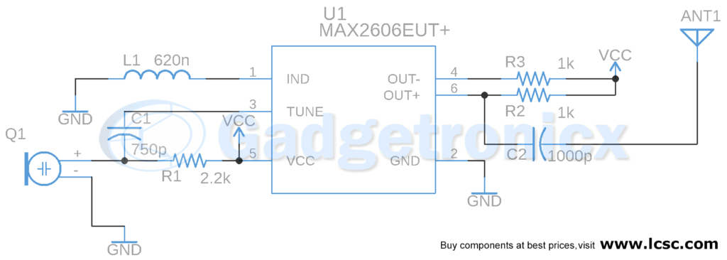
CIRCUIT DIAGRAM OF WIRELESS SPY MICROPHONE :
WORKING OF CIRCUIT :
This circuit first gets the audio signal from the mic. Here we use a simple electret Microphone, usually found in the hardware store. But it’s not the best for such audio application as it gives average sound quality and have some noise in the signal. But on the plus side it’s cheap and small in size. As we don’t want our Spy bug to be too bulky, we will go with this one.
The mic is connected to the tune pin of the IC and needs a pull up resistor(R1) to be connected to Vcc and a coupling capacitor (C1) on tune pin. This capacitor is to remove DC noise from the Audio signal, producing a much cleaner and pure Audio signal. The frequency of the audio signal is too low. It’s usually in the kHz band. It is difficult to transmit such low frequency signal to a higher distance. Therefore we need to modulate the low frequency audio signal with a high frequency carrier wave in order to achieve wider range and less interference.
MAX2606:
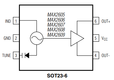
The MAX2606 IC is an 8 pin voltage-controlled oscillators (VCOs) chip widely used for wireless communications. This IC requires only an external inductor to set the oscillation frequency. Also it can operate voltage between the range of 2.7v to 5.5v. The output frequency of this IC covers from 70MHz to 150MHz frequency. Refer the MAX2606 datasheet for more information.
FIXING THE FREQUENCY:
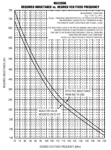
The circuit need an inductor between the IND pin and GND. The desired VCO operating frequency is set by this external inductance, L1. The value of L1 required to achieve the desired oscillation frequency is given in the datasheet. According to the datasheet the oscillator of MAX2606 can cover from 70MHz to 150MHz frequency range given that the Inductance Range(nH) has to be 140 ≤ L1 ≤ 790 of moderate Q (35 to 40). In this case we use L1 = 620nH, that will set the frequency in approximately 80MHz.
FREQUENCY RANGE:
In this example here we choose 80MHz on purpose because in most countries, the usage FM frequency range is between 90MHz and 108MHz. These set of frequencies is overcrowded by the local radio stations. We have to avoid transmitting signal in frequency within this range to avoid overlapping. For this reason we have chosen the transmitting frequency of Spy microphone to be 80MHz. This will help you to reduce interference. Many smartphones can therefore be adjusted to use this frequency band instead of the one from 88MHz to 108MHz. This saves us the money we would have to spend for a scanner or a radio.
OUTPUT STAGE:
IC MAX2606 has a positive output and a negative output. Both outputs (OUT- and OUT+) are open-collector types and needs to pull-up to VCC. Two resistors (R2 & R3) are 1kΩ pull-up resistors that are connected from OUT+ and OUT- to VCC. These resistors provide DC bias for the output amplifier and are the maximum value permitted with compliance to the output voltage swing limits. In addition, the 1kΩ resistors maximize the swing at the load. A DC-blocking capacitor(C2) is connected from OUT- and OUT+ to the antenna.
Next we connect the positive output to a 50 Ohm antenna. You can use solid wires that has a thickness of 18 – 22 gauge. The antenna length should be at least ¼ of the wavelength. If a different oscillation frequency is chosen the antenna length should be adjusted accordingly. The wavelength can be calculated according to the following formula
λ=v/f
“λ”is the wavelength, “v” is the speed of light, or about 300,000 km / s. “f” is the frequency.
POWERING UP:
Finally it’s time to power up the circuit. The supply voltage to the IC should be between 2.7 and 5.5 V. Turn on your radio then tune it to your 80MHz until you hear a feedback from the radio. And there you have it your very own nice little wireless spy microphone bug. The range that can be achieved depends very much on the characteristics of the antenna. With an antenna ¼ wavelength long (e.g. 88cm at 85MHz) the range is approximately 50m in open terrain.
PCB DESIGN:
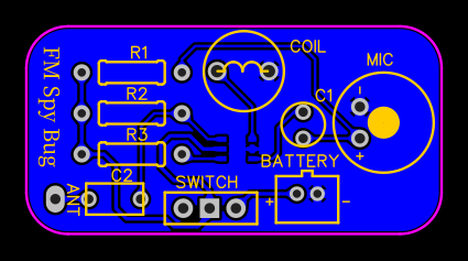 You can download the gerber files for this PCB design from below.

Hope you like this project. Do share your thoughts, feedback and queries about this project in the below comment box. Check out other projects in our website.


