Electronic dice can be a good and fun alternative to traditional dice when enjoying our board games. We have designed a Electronic dice circuit which will generate random number from 0 to 6. The specialty of this circuit is that the results are highly unpredictable due to the special modulated clock that drives the number generation. Check out other Circuits in our Circuits library
WORKING OF ELECTRONIC DICE CIRCUIT:
This circuit uses a 4 bit counter to generate a random number between 1 and 6, for this we created a modulated PWM using 2 timers 555 and a VCO. This will allow us to tell the counter to count up the number from 0 to 7 in a semi-randomly way and block the occurrence of number 0 and 7.
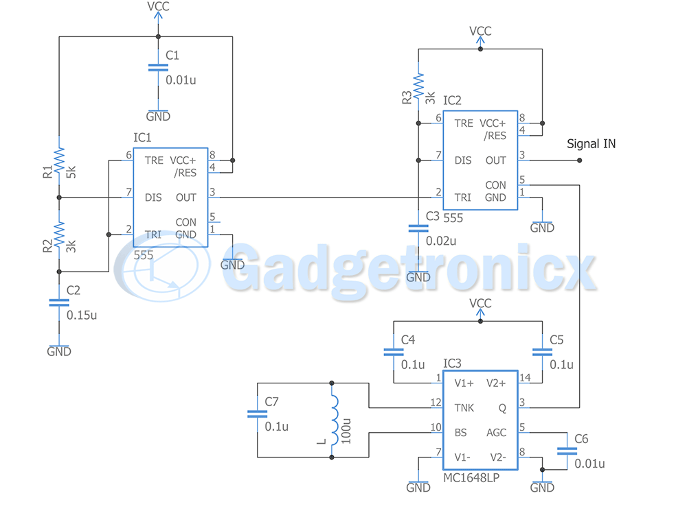
1) Clock signal generator:
The first section of the circuit generates signal input to counters to .We need the counter to count from 1 to 6 but not constantly, we should try to do it in semi-random way, we can do this making the counter to advance the numbers faster for a time and slower the rest of the “period”. This can be achieved by using the PWM signal that the counter needs but in a modulated way.
To do this we need a PWM signal and a sinusoidal signal. For this we use a 555 timer in monostable mode and a VCO based on chip MC1648LP as sinusoidal signal generator. We input these 2 signals to another 555 which acts as a modulator the result is a PWM signal modulated by the sinusoidal signal it will have two time periods” the PWM and the sinusoidal this results in shorter pulses for some time and longer pulses for some time.
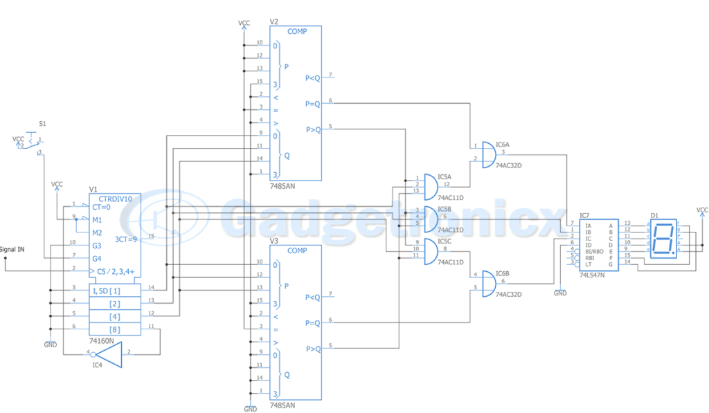
2) Counter:
The modulated signal is fed as input to counter section of this circuit. If we feed this signal to count in a 4 bit counter, this will count from 0 to 15 in a semi random way. The count will increment with each pulse but the time of this increment varies due to modulated PWM signal input.
We need to restrict the counter to count from 0 to 7, therefore 4th bit will be used as a reset signal. The switch button S1 will tell the counter to count when it is pressed. What we’ve done so far is to allow the counter to count in a semi random way from 0 to 7, but we need it to count from 1 to 6. To do this we will pass the signal to two comparator chips 7485N, this will tell us if the generated number is 0 or 7.
When this happens to be true, we will force the display to show either 1 or 6. This operation is performed using gates OR & AND. After posing this restriction we will send the resulting signal to a 74LS47N chip which will translate the BCD signal to a signal that the 7-seg display interprets to show the corresponding number.
Hope this circuit was informative to you. Check out other circuits in our website. If you have any questions or feedback about this circuit please leave them in the comment section below.