
Beat frequency indicators are used to indicate whenever frequency of a signal of our interest exceeds reference frequency. This is one such indicator circuit which uses LED’s to indicate when our signal exceeds the reference frequency. These indicator circuits can be used for both functional and aesthetic purposes. This circuit accepts any type of waveforms in input signal and reference signal.
WORKING OF BEAT FREQUENCY INDICATOR CIRCUIT:
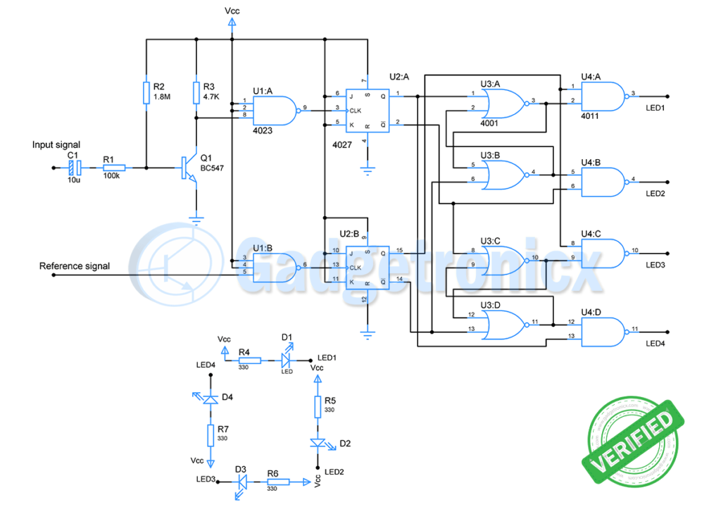
Working of this circuit starts with a common emitter transistor amplifier. The Capacitor C1 removes any DC element in the signal. The input signal will be amplified after removal of DC noise and fed to an input of NAND gate chip 4023.
The NAND gate converts the incoming signal to irregular rectangular waveforms. The width of this waveform varies with incoming signal. On the other hand, the reference signal is fed to another NAND gate which produces a regular rectangular waveform in its output.
These two rectangular waveforms are fed as a clock source to individual JK flip flops. This divides the incoming signal by two and provides a square wave signal. Not only the frequency this signal also has its mark and space ratio divided by half of its original frequency.
The output square wave from both the flip flops are gated using a NOR gate which is connected together in RS configuration. This is followed by NAND gates. The combined action of these gates will produce a rectangular pulse. The mark and space ratio of this pulse alters with the difference in phase between the two square waves.
When signal and reference signal frequency are similar or close to each other, mark and space ratio between two signals will be similar as well.
LED SETUP:
Four LEDs are used with each output of the NAND gate. The LEDs have to be arranged in a circular fashion as shown in the schematic. This will produce a nice buffering effect due to the incoming signal.
For setting up the LEDs in circular fashion the right way. Build the circuit and input manual pulse to the circuit and check which LED turns off first. Based on this arrange the LEDs in circular fashion now buffering effect will be ready.
The rate at which the LED’s alternate to produce this effect depends on the difference between input and reference signal frequency. When the frequency matches the rotation will be slow producing a slow buffer. The buffer effect will be faster when there is higher difference in frequencies.
At higher frequencies LEDs will appear to be lit all the time and there will be less flickering. This might fade the buffer effect in these cases use additional stages of flip flop to reduce the frequency further. This circuit can be powered by a +9V Vcc.
Try out this circuit. If you have any queries regarding this circuit do leave them in the comments section below. Visit our Circuit library for more circuits categorized for easier browsing.


Frank, there is no input from Q1 to U1A. As shown it won’t work. Ron
Thanks for pointing it out Ron. So silly of me to leave it unconnected. Corrected it now, thanks again.