RF also known as Radio Frequency Signal is omnipresent in today’s world. Although there are places where we receive poor reception of RF signals and a detector will come in handy in these instances to rectify this problem. Alternatively there are instances and places where we don’t want these signals to reach and in such cases we can probe the place for these signals. This Radio Frequency signal detector Circuit shown here will help you to detect these and act upon it accordingly.
WORKING OF RADIO FREQUENCY SIGNAL DETECTOR CIRCUIT:
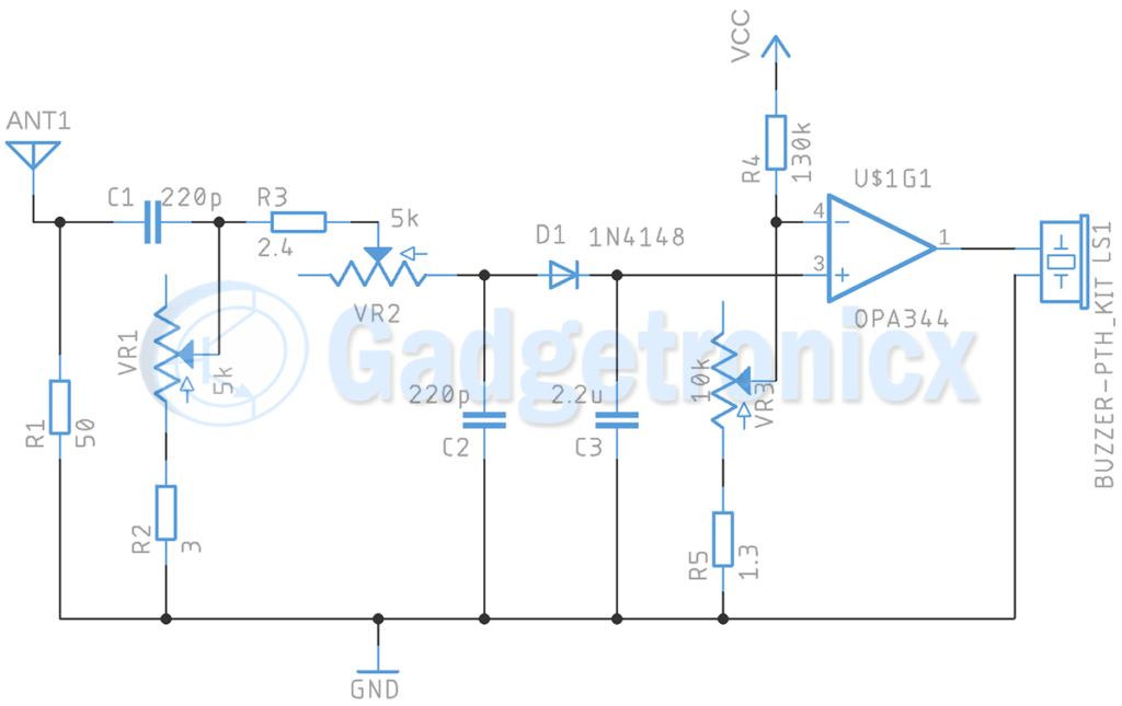
The working of this RF signal tester starts with 50 ohm Antenna which is used to receive the RF signals from atmosphere. The signal received by Antenna is then passed to a band pass filter constructed using Resistors and Capacitors. The purpose of the filter is to give user the ability to select the frequency range which our Radio Frequency signal detector needs to detect.
HIGH PASS FILTER:
Band pass filter is comprised of High pass and Low pass filter. Here in the circuit VR1, R2 and C1 forms the High pass filter. This set up a cut off point for incoming signal where it only allows signal with frequency greater than this cut off point. The frequency allowed via high pass filter is given by the formula fc = 1 / 2πRC
Applying the values of VR1, R2 and C1 in the above formula. When the POT VR1 is in minimum position the resistance of VR1 will not affect the circuit, hence R1 3 ohm will be the only resistance source for this high pass filter.
When VR1 is set to its maximum position the frequency selection range will decrease. Here the VR1 value will be 5k.
fc = 1 / 2 x 3.14 x ( 3 + 5k ) x 200 x 10-12
= 1 / 6911960 x 10-12
= 145 Khz
Here by adjusting the Potentiometer VR1, we can alter upper cutoff frequency from 145khz to 240Mhz. Here any signal with frequency greater than this cutoff frequency will pass on to High pass filter.
LOW PASS FILTER:
The output signal from the High pass filter is then passed to Low pass filter which is constructed using R3, VR2 and C2. This Low pass filter allows signal with frequencies less than its cut off frequency. The cut off frequency of a low pass filter can be calculated using the formula
fc = 1 / 2πRC
So when the POT is set to its minimum position then the lower cut off frequency will be 300MHz. And when the POT is set to its maximum state then the lower cut off frequency will be 145khz. This filter will allow signal with frequencies below these cut off frequencies. This can be set to anywhere between 145KHz and 300MHz. By altering the cut off frequencies of High pass and Low pass filter you will have the ability to select frequencies you need to detect by this circuit. Also remember that set resistance of First Potetntiometer VR1 (High Pass) should be lower than Second one VR2 (Low Pass) or the entire input signal will be filtered out.
The filtered signal will reach to D1 which rectifies the signal and in combination with C3 maintains the signal in stable state. We use Op-Amp to compare this signal with reference voltage which can be set using POT VR3. The output of Op-Amp will turn the buzzer ON when the sensed signal by Antenna is within the range of frequency set by High pass and Low pass filter. And by substituting the R and C values in High pass and Low pass filters you can modify this circuit to detect signal of any frequency.
Sorry sir, I still don’t understand the reason why OPA344 is used. Based on its datasheet, the GBP is only 1 MHz, thus it’s rendered useless on RF signal, or am I wrong sir?


Hello, please send me the instructions for making an electronic circuit that has a frequency between 0 and 20 kHz.
Is 50 ohm antenna is mandatory
This circuit is working or not for detecting desired RF frequency
Sorry sir, I still don’t understand the reason why OPA344 is used. Based on its datasheet, the GBP is only 1 MHz, thus it’s rendered useless on RF signal, or am I wrong sir?
This circuit will work or not because as per data sheet Pin 2 & pin 3 will be input and pin 6 will be output ?
Shown circuit diagaram is different