People / Object counter circuit have a wide variety of applications in Banks, Hospitals, factories etc. This project focuses on building an effective counter using IR as a sensing element and capable of counting from 0 to 999. This project uses Two simple IC’s ( IC 555 & IC 4026 ) with IR transmitter and Receiver to detect the incoming people/object.
This Project comprises of Three parts
IR Transmitter
IR Receiver
7 Segment drivers
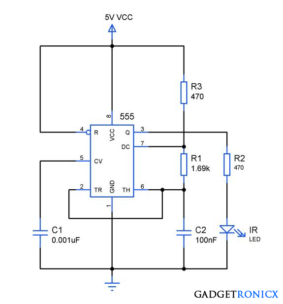
IR TRANSMITTER:
Freq = 1.45 / ( R3 + 2R1 ) C2IR transmitter was wired around Astable multivibrator using IC 555. As we all know that multivibrator produce square wave pulses and we gotta fix the frequency of the output signal as 38 Khz since we are about to use TSOP 1738 an Infra red sensor which is capable of detecting signals of 38 Khz. The frequency of the astable depends on R1,R3 and C2. So lets do some math
So we have fixed the IR frequency of 38 Khz and now Transmitter part is done.
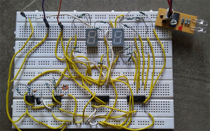
Please note that i have used a simple IR transceiver module (brown board – right top) for this project to make things simple. You can use use IR module like i did if you have any. If not build the IR transmitter using IC 555 as shown in above circuit. The receiver part was given in the below circuit diagram.
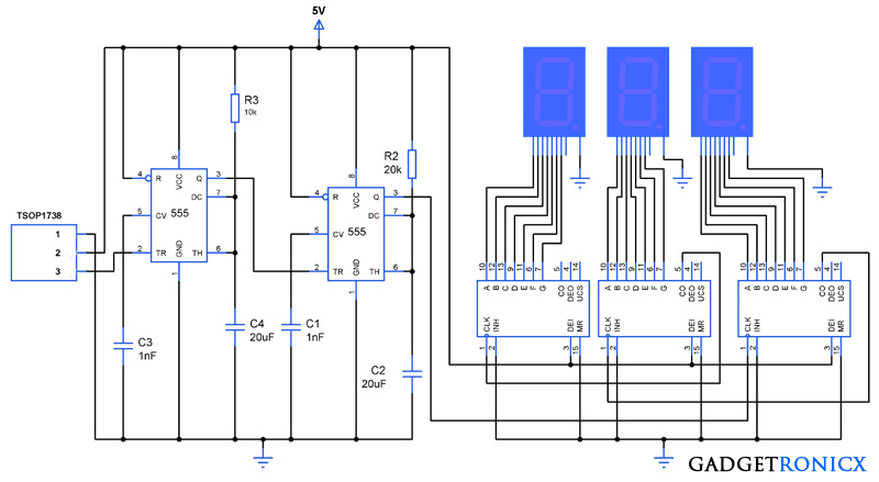
IR RECEIVER AND 7 SEGMENT DRIVER:
The sensed output was fed into trigger input of the monostable multivibrator using IC 555. As we all know that Multivibrators gives high output when low signal as fed into its trigger and low output when high signal is fed. Two multivibrators was cascaded to prevent multiple increments in the counter since using a single multivibrator changes the output with every low to high or high to low transition in trigger pin.The above circuit diagram comprises of both Infra Red Receiver as well as 7 segment driver. The IR signal is sensed by TSOP 1738 which is capable of sensing the IR signals of 38 Khz frequency. This TSOP will give high signal as output when IR signal is sensed and low signal when IR falls on it. The third pin of the TSOP gives the output and its fed into next stage of the circuit.
IC 4026
Next stage of the circuit is 7 segment drivers which is done by three IC 4026 which is a 7 segment display decade counter. This IC is capable of incrementing the digits in 7 segment with clock input in the CLK pin. The output from the monostable multivibrator forms the clock source for this IC 4026. Read more about 7 Segment interface with IC 4026.
WORKING:
The transmitter and Receiver was initially aligned and this makes the TSOP 1738 to give low signal to the multivibrator which in turn gives high at the output and this forces the 2nd Multivibrator to give low signal to the CLK pin of the right most IC 4026. When the IR beam in interrupted the TSOP gives high output which in turn makes the Multivibrator 1 to give low signal trigger to the 2nd multivibrator.
The low signal input pushes the output of Multivibrator 2 to high state thereby a successful transition occurs and this forms a single clock pulse input to the IC 4026. Thus this makes the IC to increment a single value in the 7 segment. Now cascading three segments will enable us to display count up to 999 which was done by connecting the CO (Clock Out) pin of the IC 4026 to the input clock pin of the preceding IC 4026.
Whenever IC 4026 finishes counting from 0 to 10 it gives out a logic transition in its CO pin which sources the clock for preceding IC at CLK pin which in turn increments the value by 1. By this way three IC’s work together to display digits from 000 to 999.
WORKING VIDEO:
NOTE:
You can increase the count value by adding 7 segments along with IC 4026 by connecting the CO pin output of the Preceding IC to its CLK pin.
You must use two multivibrator or else you will obtain two increments for a single incoming person/object.
Hey Frank! can you please upload the layout of this circuit, so it will be easy for students to understand and make it. Also how to replace the IR transmitter circuit in the video with the TSOP 1738. Or just post the connection of your IR transmitter circuit with the main circuit. Please help me as I’m making a project on this. Thanks!
The circuit diagram is already given in the article i don’t understand what you exactly mean by layout please clarify. Here is how to make IR module link you could use for this project https://www.gadgetronicx.com/infrared-sensor-module-circuit/ .
Using TSOP1738 seems to be more easy to implement this project so i have made the circuit design that way. You can use an IR sensor module as i did in my project build. The working principle remains the same. Hope it helps.
Adesh,
That’s current limiting resistor to prevent SSD from getting damaged. Omitted in the circuit to keep it simple. Use 200 ohm resistor that will do good
Mehdi,
Connection video will take too long i guess, refer the circuit diagram and chip datasheet for making the connections, that will be the best way to do it.
Hi Mehdi,
Thanks for the compliment. The above image is just for displaying the one i built the connection looks scary even for me. So please refer the circuit diagram in which i have mentioned all the components name and their corresponding values.
Hope i made it clear,let me know the outcome if you build it.
Yes you are right. Once connection build it difficult to re-arrange it.
1. I just want to know that what and how many equipment required for you to develop circuit ?
2. Is it possible for you to re-create it and post here full image with connection ? I know it’ll be difficult for you But If you can, not only me all students will find it helpful.
Mehdi,
I see what you are suggesting, the above circuit from Circuit Digest seems very much similar to my circuit. It also contains how you can set up an infra red sensor module on your own as well. I think it will do for guiding you to make all the connections right.
hey, i am using the op amp lm358 as comparater, and a black photo diode. my circuit gives zero response and the seven segment displays show 08! its my project and do therefore need your help. thanks.
Greetings,
i have some question regarding the circuit ? lets say if i want to build a simple counter with IR , would i need two of the IC555? and regarding the the c codes?
should i able to run this on protheus?
Kishan,
Yes you do want two of those or simply substitute with a microcontroller, that also makes the circuit more simple. Of course you can run this in proteus.
Shobhit,
You can find the description if you run a search over the internet. Please note the the module which i built slightly differs from the circuit which is shown, However both ways you can achieve the results. TSOP1738 is nothing but a IR receiver that can detect IR signals of 38khz frequency. However which is used is a simplified approach there which the module itself emits the IR signal using IR LED and detects the reflected signal using Photodiode affixed along with the IR LED. Hope it helps.
Jasmine,
Its not white LED. Its an IR LED and detector. It forms a IR sensor module. I have given the whole module as a single block in the schematic to make it less complex. If you are wondering about working of a IR sensor pair then do visit this link https://www.gadgetronicx.com/infrared-sensor-module-circuit/
I dont think this counter circuit will do efficient counting when too many people comes closer in a queue also where do you suggest to install the IR receiver and transmitter?
Sure it will, but you have to manage your queue through a turnstile. No counter will do proper counting when the queue is not properly managed. Talking about the placement of IR TX and RX , it should be installed on the roof or the over the head of the people coming in.

 The sensed output was fed into trigger input of the monostable multivibrator using IC 555. As we all know that Multivibrators gives high output when low signal as fed into its trigger and low output when high signal is fed. Two multivibrators was cascaded to prevent multiple increments in the counter since using a single multivibrator changes the output with every low to high or high to low transition in trigger pin.The above circuit diagram comprises of both Infra Red Receiver as well as 7 segment driver. The IR signal is sensed by TSOP 1738 which is capable of sensing the IR signals of 38 Khz frequency. This TSOP will give high signal as output when IR signal is sensed and low signal when IR falls on it. The third pin of the TSOP gives the output and its fed into next stage of the circuit.


Hey Frank! can you please upload the layout of this circuit, so it will be easy for students to understand and make it. Also how to replace the IR transmitter circuit in the video with the TSOP 1738. Or just post the connection of your IR transmitter circuit with the main circuit. Please help me as I’m making a project on this. Thanks!
Hi Shameek,
The circuit diagram is already given in the article i don’t understand what you exactly mean by layout please clarify. Here is how to make IR module link you could use for this project https://www.gadgetronicx.com/infrared-sensor-module-circuit/ .
Using TSOP1738 seems to be more easy to implement this project so i have made the circuit design that way. You can use an IR sensor module as i did in my project build. The working principle remains the same. Hope it helps.
hello sir….
resistor shown in video in between ssd and driver ic but shown in the circuit digram…
plz tell me the values of resistor used
Adesh,
That’s current limiting resistor to prevent SSD from getting damaged. Omitted in the circuit to keep it simple. Use 200 ohm resistor that will do good
Which type of 7 segment display we have to use for this project common anode / common cathode or we can use both?
Subham,
You should use common cathode in this circuit.
Hello, Can You make connection in video with showing all equipment ?
It will be very helpful for all students.
Thank You.
Mehdi,
Connection video will take too long i guess, refer the circuit diagram and chip datasheet for making the connections, that will be the best way to do it.
Hello Frank,
First of all I Like your post. It such a very nice and helpful. I need just only two help.
Help 1. Kindly mention all equipment name ( with used quantity ) in the post so I and other people can get it easily.
Help 2. Please also cover all connection in the given image so we fell it easy to connect.
https://www.gadgetronicx.com/wp-content/uploads/2014/08/peopl-or-object-counter-project.jpg
Thank You. I hope you will review my request and really need your help.
Mehdi.
Hi Mehdi,
Thanks for the compliment. The above image is just for displaying the one i built the connection looks scary even for me. So please refer the circuit diagram in which i have mentioned all the components name and their corresponding values.
Hope i made it clear,let me know the outcome if you build it.
Hello Frank, Thanks for reply me.
Yes you are right. Once connection build it difficult to re-arrange it.
1. I just want to know that what and how many equipment required for you to develop circuit ?
2. Is it possible for you to re-create it and post here full image with connection ? I know it’ll be difficult for you But If you can, not only me all students will find it helpful.
Mehdi.
hi mehdi
plzz app mjy is project ki report send kr skte hn?
For example : check out this circuit diagram. I need this.
http://circuitdigest.com/sites/default/files/circuitdiagram/Object-Counter-Circuit-Diag.gif
Thank You.
Mehdi,
I see what you are suggesting, the above circuit from Circuit Digest seems very much similar to my circuit. It also contains how you can set up an infra red sensor module on your own as well. I think it will do for guiding you to make all the connections right.
hey, i am using the op amp lm358 as comparater, and a black photo diode. my circuit gives zero response and the seven segment displays show 08! its my project and do therefore need your help. thanks.
Kamulegaya,
Please post your circuit so that i can look and suggest a solution.
Greetings,
i have some question regarding the circuit ? lets say if i want to build a simple counter with IR , would i need two of the IC555? and regarding the the c codes?
should i able to run this on protheus?
Kishan,
Yes you do want two of those or simply substitute with a microcontroller, that also makes the circuit more simple. Of course you can run this in proteus.
Can i get a complete description of the components required and if possible a description of difference between TSOP 1738 and IR sensing Module.
Shobhit,
You can find the description if you run a search over the internet. Please note the the module which i built slightly differs from the circuit which is shown, However both ways you can achieve the results. TSOP1738 is nothing but a IR receiver that can detect IR signals of 38khz frequency. However which is used is a simplified approach there which the module itself emits the IR signal using IR LED and detects the reflected signal using Photodiode affixed along with the IR LED. Hope it helps.
where are the two white led in the circuit?
Jasmine,
Its not white LED. Its an IR LED and detector. It forms a IR sensor module. I have given the whole module as a single block in the schematic to make it less complex. If you are wondering about working of a IR sensor pair then do visit this link
https://www.gadgetronicx.com/infrared-sensor-module-circuit/
I dont think this counter circuit will do efficient counting when too many people comes closer in a queue also where do you suggest to install the IR receiver and transmitter?
Sure it will, but you have to manage your queue through a turnstile. No counter will do proper counting when the queue is not properly managed. Talking about the placement of IR TX and RX , it should be installed on the roof or the over the head of the people coming in.
im bit confused. where is the transmitter circuit? and where are the 2 white leds in the schematic diagram?