
Dull cupboards is something which I always hate like everybody else. Especially when we need to pick something up from cupboard it takes forever to do that due to dull unlit cupboards. This cupboard lighting circuit can be a solution to the above problem where it uses only minimal components and very easy to put together and wire it to your cupboard.
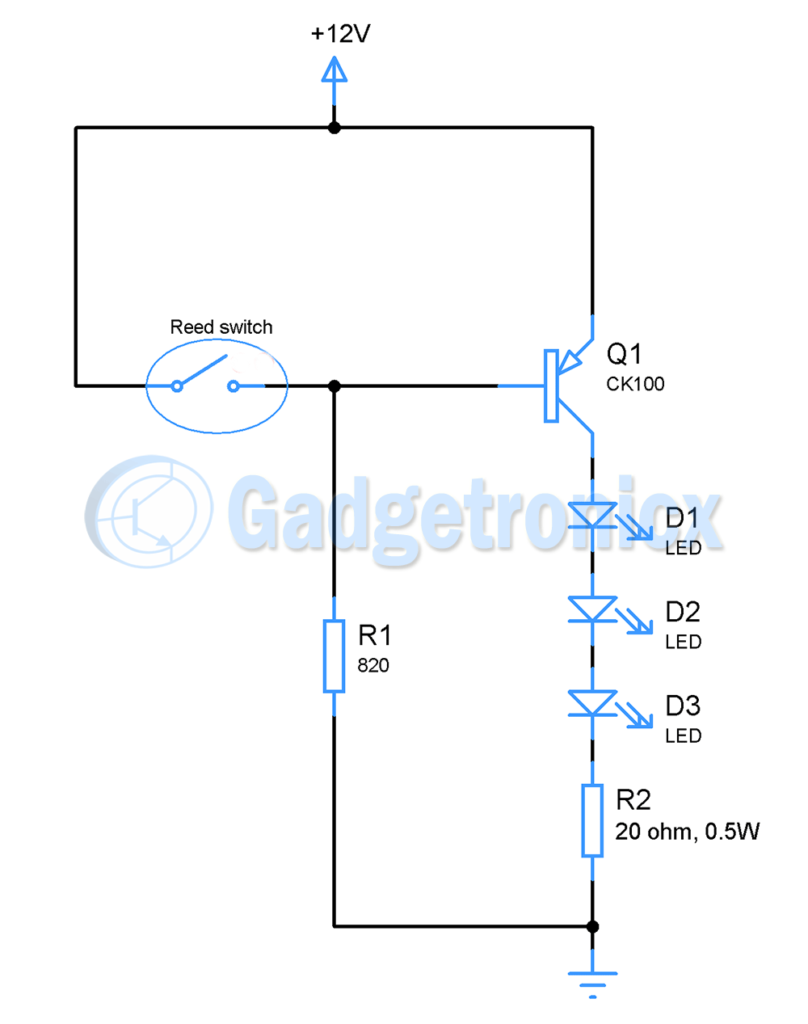
CUPBOARD LIGHTING CIRCUIT DIAGRAM:
The working of this circuit starts with magnetic reed switch which acts as an activator in the circuit. Place the reed switch on one side of cupboard so that when door with magnet affixed is closed it should activate the reed switch. Placement of reed switch and magnet is of dire important for working of this circuit.
The PNP transistor CK100 serves as a switch in this circuit. When the base of transistor is pulled high the transistor will be in off state, while it is pulled low transistor will be forced to on state. So when the door is closed it activates the reed switch which in turn closes the circuit and pulls the base of transistor to Vcc. This will force the transistor to off state. Once the door is opened the resistor R1 will pull the base to low state. This will activate the transistor and force the transistor to ON state.
When the transistor is in ON state. The current started flowing from emitter to collector which makes the LED’s to glow and light up your cupboard. The important thing to keep in mind is that we have used 0.5 Watt LED’s in this project which will consume roughly about 150mA which is very large compared to the usual LED’s. Each of these LED’s drop about 3.2v which sums the total voltage drop by LED’s as 9.6v. This means the current limiting resistor connecting LED’s need to drop about 2.4v with 150ma current flowing through it.
Voltage drop of 3 LED’s = 3 x 3.2 = 9.6v
R2 = ( 12 – 9.6 ) / 150mA
= 16 ohms
= 20 Ohms ( rounded off )
Calculating the power dissipating in this resistor gives about 0.3W.
P = VI
= 2.4 x 150mA
= 0.36 Watts
It is a good practice to use resistor with wattage rating twice the actual power consumption. So here I have used a resistor of 20 ohms rated 0.5W. The base resistor value of transistor is calculated by
R1 = Vcc – Vbe / Ib
I have chosen Ib as 15mA since it is a good practice to choose 1/10 of collector current as Ib to force them into saturation region and turn the transistor ON.
R1 = ( 12 – 0.6 ) / 15mA = 760 Ohms
= 820 Ohms ( Rounding off to nearest value )
This circuit can be assembled in a general purpose PCB and takes only very less space since the components involved is very less.
NOTE:
- Use power supply which can supply up to at least 500mA.
- Position of magnet and reed switch is very critical and might need some trial and error to get it right
- The main disadvantage of this circuit is that when cupboard door is closed the circuit will consume about 15mA of current due to the current path provided via R1, so a continuous DC power supply is highly recommended.


