Digital weighing scales replaced the traditional analog scales due to it’s accuracy and ease to use in our homes. I have to recently repair a malfunctioned Digital weighing scale in my home. I realized that it would if I did a tear down of this and share info about core electronic parts inside this scale and how it all works together.
Weighing scale:
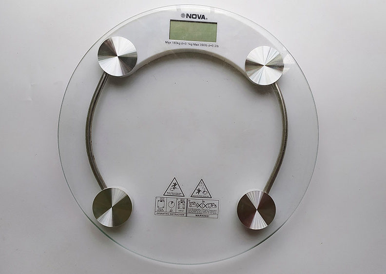
This scale body was made out of glass. It has LCD to display the results. The four steel knob like structures houses the sensors which is responsible for measuring our body weight. As per the instruction manual for this product, the user should align his /her legs over these knobs for maximum precision in their results.
Backcasing:
When flipped over there were four rubber pads that supports the weighing scale and keep them level in surfaces. Additionally this rubber pads cover the load cell sensor that is used to measure the weight of user.
Load cell sensor:
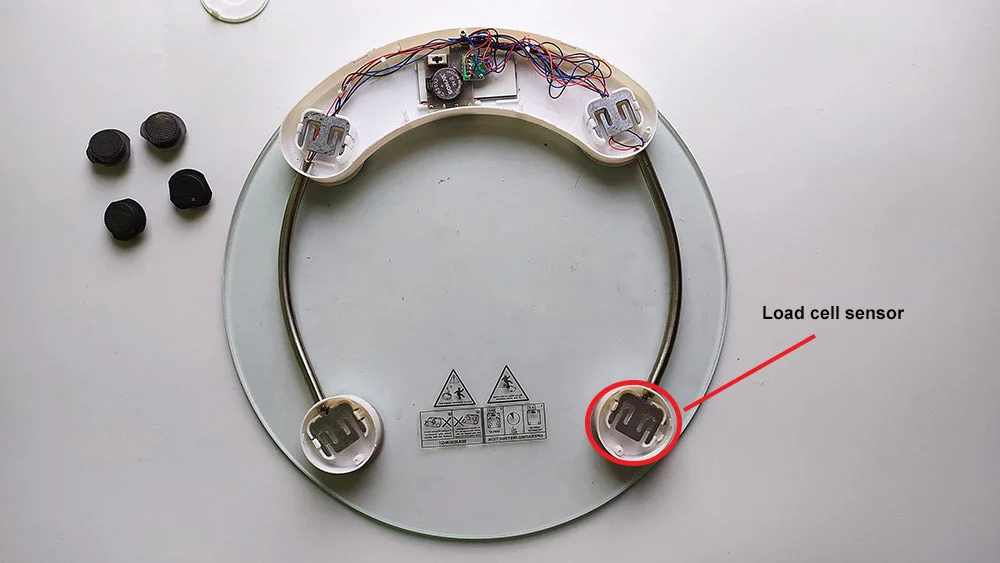
Upon removing the rubber pads I can see there are about 4 load cell sensors. Typically load cells measure force applied on it and in turn produces a output voltage equivalent to input force. The sensitivity that is the change in output voltage of load cell per kilogram or pound weight input depends on the type of load cell used. Unfortunately this doesn’t have any part markings on it. These load cell sensors are placed in a way that users feet will exert force on these sensors. This in turn will be converted to weight of the user.
Circuit board:
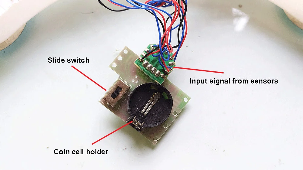
Here is the circuit board that is responsible for operating the individual components in weighing scale. The circuit is powered by a 3V coin cell battery. Also there is a sliding switch to toggle between OFF, KG and LB ( pounds ) mode.
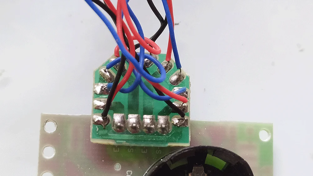
The 4 sensor inputs are fed into the circuit board. It looks like the red wires are actual output from load cells. These wires connect to a female header and connects to the main circuit board.
Chip on board:
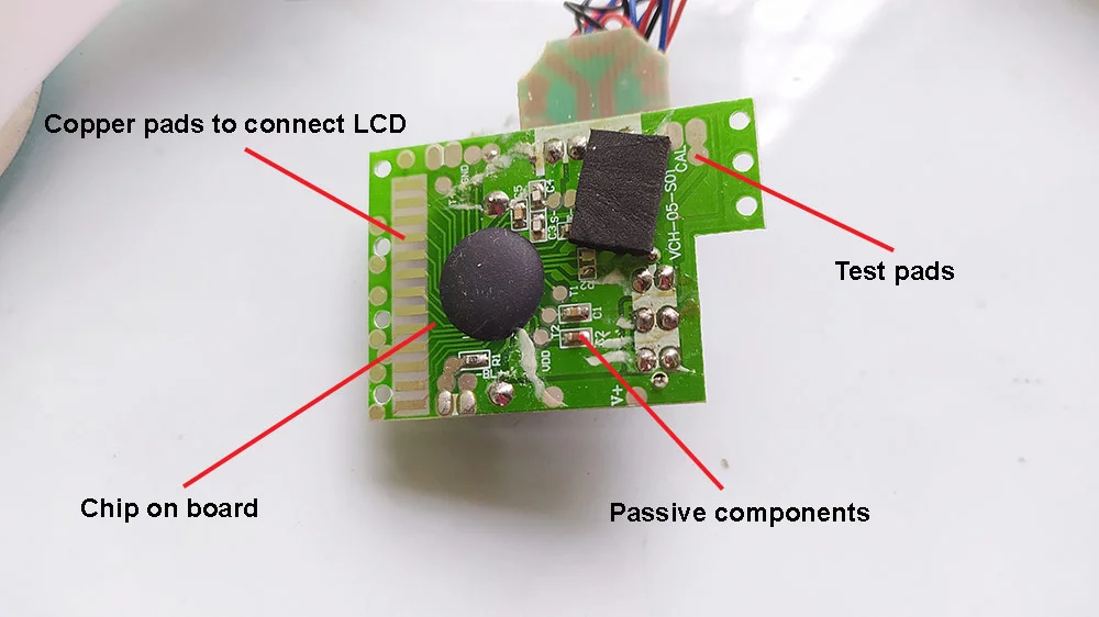
To my disappointment the circuit uses a chip on board to process the input from sensor and display it on LCD screen. This chip on board method is practiced by manufacturers where Integrated chips are directly wired to PCB board and covered by epoxy. This looks like a black blob as shown in the above image.
This method of manufacturing greatly reduces the manufacturing cost when companies mass produce these boards. Also it will hide proprietary designs making it impossible to recreate this product using this design. I assume this chip holds a LCD driver and modules to process sensor inputs.
There are other passive components such as resistors and capacitors in this board. Couldn’t make out the functionality of these components due to COB. There are also test pads that would have helped manufacturers to test the circuit.
LCD interface:
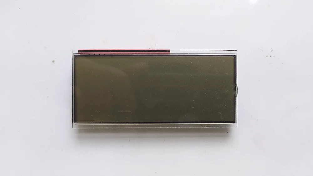
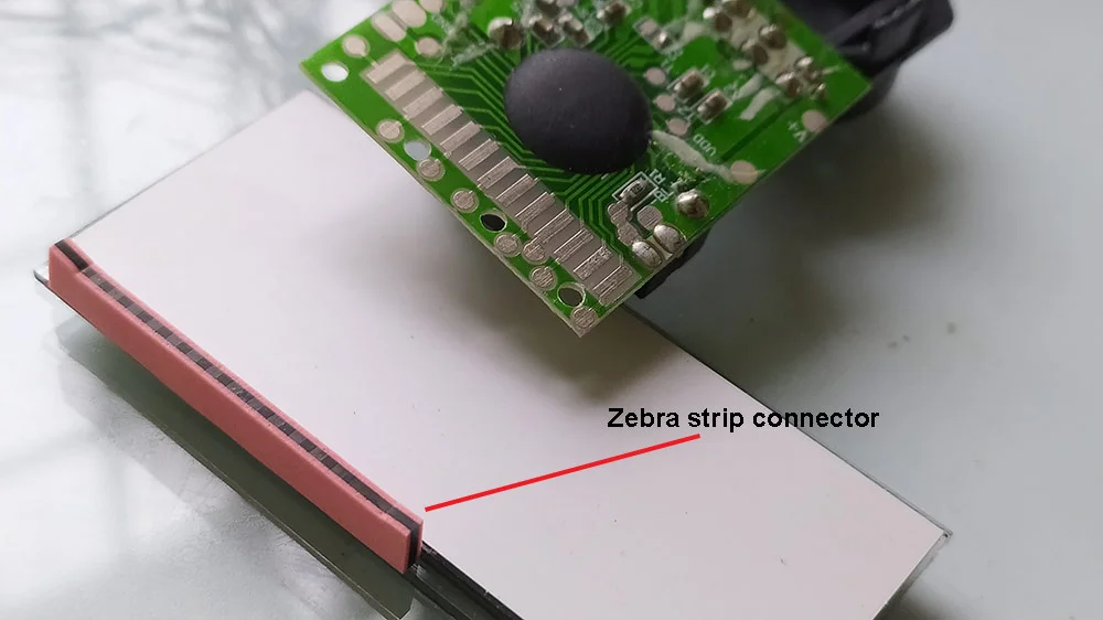
This weighing scale uses a TN LCD display, I came to know about this by surfing around and looking for similar LCDs. These types of LCD is of low cost and draws very minimal current to operate.
This LCD is connected to the circuit board using a zebra connector. This zebra connector consists of alternating conducting and insulating layers in a rubber surface. When the LCD is fixed on the board, the conductive layers come in contact with the copper pads in PCB allowing the Chip on board to send signal to LCD and display necessary data in it.
That’s all with this digital weighing scale. It would have been great if circuit board didn’t have the Chip on board which hid some of the key details to understand working of this weighing scale. There are methods to remove the epoxy from chip on board and expose what’s inside. But it is destructive process and it is very likely the circuit will cease to work.
Hope this tear down was informative to you. I will look to tear down other devices and gadgets to explore the core electronics used in it and figure out how it operates. If you have any feedback or comments leave them below.

 This scale body was made out of glass. It has LCD to display the results. The four steel knob like structures houses the sensors which is responsible for measuring our body weight. As per the instruction manual for this product, the user should align his /her legs over these knobs for maximum precision in their results.
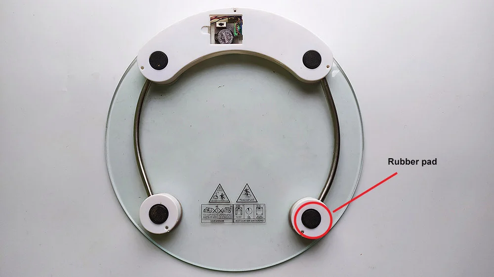
 Upon removing the rubber pads I can see there are about 4 load cell sensors. Typically load cells measure force applied on it and in turn produces a output voltage equivalent to input force. The sensitivity that is the change in output voltage of load cell per kilogram or pound weight input depends on the type of load cell used. Unfortunately this doesn’t have any part markings on it. These load cell sensors are placed in a way that users feet will exert force on these sensors. This in turn will be converted to weight of the user.