Passive Infra red sensor also known as PIR sensors is capable of detecting motion or movement within a certain range. These type of sensors have wide range of applications in our daily life and it is essential to learn the interfacing method. This article is going to demonstrate the PIR motion sensor interface with AVR microcontroller.
APPLICATIONS OF PIR SENSOR:
Lets see some of the common applications of PIR sensor for better understanding.
Automated doors in shopping malls.
Lifts
Garden lights
Parking areas
PIR SENSOR:
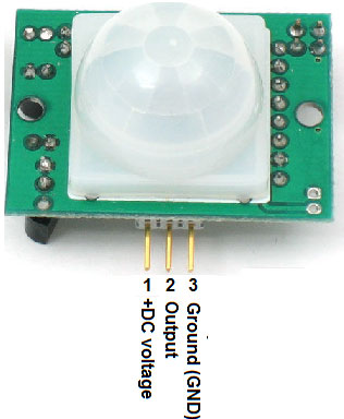
The PIR sensor detect only bodies (hot materials and living objects) in motions not the static ones. This sensor uses Infra red beam to detect the motion and only covers a certain space based on the sensor model, i advise you to go through the manufacturer datasheet to know about the range. This sensor module gives only two output states that is logic High 1 which is equivalent to 3.3 V and logic low 0 equivalent to 0 V.
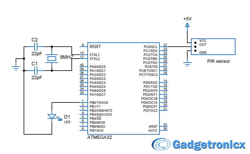
SCHEMATIC DESIGN:
WORKING:
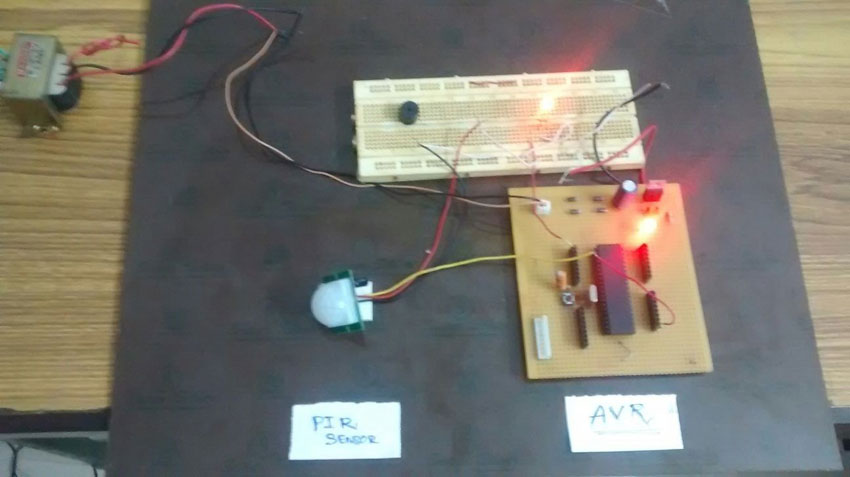
The PIR sensor is interfaced with Atmega32 AVR microcontroller to detect the motion around the environment. Atmega32 considers any voltage between 2V to 5V as logic high. Hence PIR sensor is directly interfaced to the input pin of the controller.
The circuit shown above will read the status of the output of the PIR sensor and switch ON the LED when there is a motion detected and switch OFF the LED when there is nothing. Output pin of the PIR sensor is connected to PortC.0 pin of the atmega32. LED is connected through PORTB.0 of the microcontroller.


please i need complete project on passive infared detector using AVR microcontroller
Did you mean to define your CPU clock to be 8MHz or 800KHz
Olajide,
Yes thanks for pointing it out. It was updated correctly now.