
Ever thought of controlling your home using voice. If you are the one who fascinated it as I do, this project might help you do it for real. Voice powered products are already taking over the market and this voice controlled home project will enable you you to build one for your own.
We have developed a prototype of this “Voice controlled home automation” project and we are going to share the steps to build it. We are pretty sure that this will help elderly and disabled in home also it will give control of places with difficult reach.
APPLICATIONS:
- Turning appliances ON/OFF with minimal effort.
- Lawn irrigation systems
- Heat, ventilation and air conditioning control
- Optimizing use of low cost electricity.
HARDWARE REQUIREMENTS:
- Arduino
- Motor driver & DC motor (fan)
- Led ( Simulation of TV)
- Relay (12v) bulb ( 7w )
- Bluetooth module (hc-05)
- Smart phone
- Servo (door)
SOFTWARE REQUIREMENTS:
- AMR Voice app
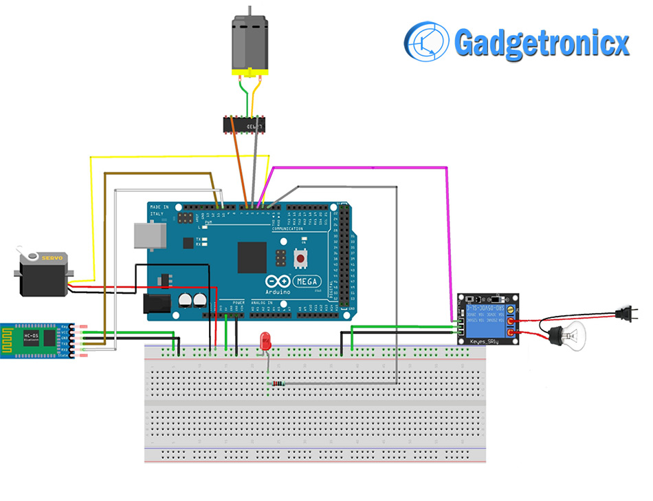
SCHEMATIC DIAGRAM OF VOICE CONTROLLED HOME AUTOMATION:
AMR VOICE APP:
This Application is an important constituent for this project. This app uses your internal Voice recognition in your smartphone to send the data serially to the Bluetooth connected to your Arduino. This application data takes special data format
- * – Start bit of the data
- # – Stop bit of the data.
We need to incorporate these start and stop bits in our code. For example if we give “ON” voice command by speaking through this app, it will reach the Arduino as “*ON#“. You can download this Android app in Playstore. Sorry this Application is not available in iOS platforms and i couldn’t find any alternatives as well.
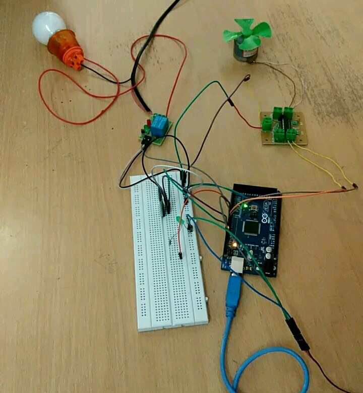
WORKING EXPLANATION:
As you can see in the schematic i have add four activators
- Relay board – For activating the bulb
- DC motor with L293D – Fan
- Servo motor – Closing and opening of door
- LED – TV control ( Demonstrative purpose)
The communication between Bluetooth module is established using android phone and AMR voice app. Initially turn on the Bluetooth in your phone, pair and connect with module HC-05. You will be all set give your voice commands to your phone which in turn sends it to BT module and it forwards to Arduino in serial data representation.
COMMANDS:
I have used the following commands to make my voice controlled home.
- light on
- light off
- fan on
- fan off
- door open
- door close
- tv on
- tv off
CODE:
#include<SoftwareSerial.h>

#include<Servo.h>

#define RELAY 4       //initialize digital pin 4 to relay

SoftwareSerial  BT(11, 10); //initialize bluetooth TX and RX to pin11 and pin10 of
                                                    arduino
String voice;

Servo myservo;   //create servo object to control a servo

int pos = 90;  // variable to store the servo position

void setup()
{
  BT.begin(9600);

  Serial.begin(9600);

  pinMode(2, OUTPUT);  // initialize digital pin 2 as an output.

  myservo.attach(3);  // attaches the servo on pin 3 to the servo object

  pinMode(RELAY, OUTPUT);

  pinMode(5, OUTPUT); // intialize digital pin 5 to one end of DC motor

  pinMode(6, OUTPUT); // intialize digital pin 6 to one end of DC motor

}

void loop()
{

  while (BT.available())      //Check if there is an available byte to read
  {

    delay(10);              //Delay added to make thing stable

    char c = BT.read();

    if (c == '#')

    {
      break;             //Exit the loop when the # is detected after the word
    }

    voice += c;           //build the string
  }

  if (voice.length() > 0)
  {

    Serial.println(voice);

    if (voice == "*TV on")
    {
      digitalWrite(2, HIGH);   // led turn on
    }

    else if (voice == "*TV off")

    {
      digitalWrite(2, LOW);   // led turn off
    }

    else if (voice == "*door open")
     {

      for (pos = 90; pos <= 180; pos++) // goes from 0 degrees to 90 degrees
        // in steps of 1 degree
      {

  myservo.write(pos);  // tell servo to go to position in variable 'pos'
        delay(15);    // waits 15ms for the servo to reach the position
      }
     }

    else if (voice == "*door close")
    {

 for (pos = 180; pos >= 90; pos--) // goes from 90 degrees to 0 degrees

 {

    myservo.write(pos);   // tell servo to go to position in variable 'pos'

    delay(15);               // waits 15ms for the servo to reach the position

  }

}

else if (voice == "*light on")

{

  digitalWrite(RELAY, 1); // turn the LIGHT ON

}

else if (voice == "*light off")

{

  digitalWrite(RELAY, 0); // turn the LIGHT ON

}

else if (voice == "*fan on")

 {

  analogWrite(5, 0); //DC MOTOR rotates in anticlockwise

  analogWrite(6, 50);

}

else if (voice == "*fan of")

{

  analogWrite(5, 0); //DC motor  won't rotate

  analogWrite(6, 0);

}

else if (voice == "*low")

{

  analogWrite(5, 0);

  analogWrite(6, 50);

}

else if (voice == "*fast")

{

  analogWrite(5, 0);

  analogWrite(6,400);

}

else if (voice=="*medium")

{

    analogWrite(5,0);

    analogWrite(6,75);

}


voice = "";         //Reset the variable

}

}
WORKING VIDEO:
MAKERS:
![]()
- Mohan Rama Raju
- Harika
- Sai Kumar Goud


can i use Arduino UNO instead of Arduino Mega in this project?
Yes u can use
How much power is require to operate the circuit?
can some gives the detials where to buy component like motor driver,servo door. etc
Code gets uploaded but when we give commands,tv,lights are no getting on
Hi Tarak,
Have you tested your BT module. Also test your voice command, where some voice commands won’t be interpreted exactly like you speak. Words might change you may want to adjust the code accordingly.
codeis not ……..but leds are not getting on
can i get the clear circuit diagram of this
Anusuya,
The diagram shows the connection in a breadboard it was done using Fritzing online eda tool. It will be different from traditional circuit diagram. I would suggest you to compare the above layout with a bread and you will be able to figure out the circuit diagram.
content in SoftwareSerial.h & servo.h
this code is not working for me ,can anyone help me with corrected code?
It perfectly Works .. !
Thanks Gadgetronicx 🙂
Ali,
Welcome
helllo brother how to connect all the elements??? please help me….
helllo brother how to connect all the elements???
Salmanur,
Kindly follow the schematic diagram.
BEST !! <3