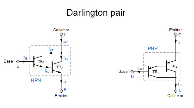
Transistors the most valuable component used in electronics. The main two functions of a transistor is to act as a switch and as an amplifier. But when using transistor as a switch we might come across a situation where the gain of our transistor is not sufficient enough to drive the load connected to it.
In these cases we use a special transistor arrangement called Darlington pair, where transistors are connected together as shown above. The transistors can be either same or different. The darlington transistor pairs give high current gain which ranges in around 1000 whereas a single transistor is only capable of giving gain from 100 to 200. Thus this allows a small base current to switch large loads.
Darlington transistor pairs are extremely useful where your single transistor couldn’t drive the load and you could add another transistor to it and drive the desired load.
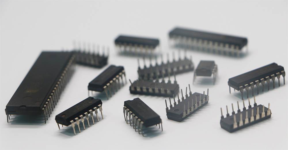
Over killing a circuit design often occurs among designers where they try and integrate as many components as possible to complete the design. This is not really necessary since plenty of modern cost effective MCU’s in the market are quite capable of replacing the parts making your design less bulky and cost effective. Combining right analog parts or digital chips with Microcontroller will reduce the size of your circuit and increase the efficiency quite dramatically.
Modern microcontroller’s comes in small packages ( 6 pins, 8 pins ) and have features like Timer, PWM, Serial communication, ADC and much more. Occupying less space with some advanced features we must look for spots in our circuit to substitute bulk chips / components with these MCU’s to achieve cost versus performance benefits in our design.
8) PWM SIGNALS:
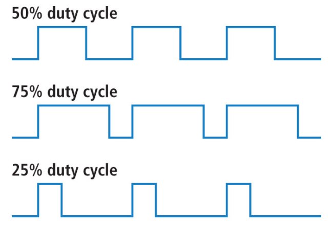
PWM signals have wide range of applications, however for this tip we are going to see its ability on saving power on LED and motor circuits. As you know PWM is a type of modulation where you can modify the width of pulse. For a 60hz PWM signal with 70% duty cycle, pulse will stay ON for 70% and 30% will be off for the total time period.
When we use these signals to drive a LED or motor, current will flow only for 70% of their total time and no current will go through during the OFF time. This happens since the PWM signal at 60HZ is too fast and when we drive LED’s or motor which are pretty slow to react to this frequency. Hence they will give an impression that it is staying ON all the time meanwhile reducing the power consumed.
To explain this better consider a 60hZ & 70% duty PWM signal driving a LED with forward voltage of 3v and 30mA current consumption. So the power consumed will be
3v * 30mA = 90mW
Now since the LED is ON only for 70% of the time, actual power consumed will be 90mW * 70 / 100 = 63mW. So when you design a LED or motor circuit especially if it is a heavy current draw one dedicate some space for PWM generation circuitry, this will save you a lot of power. And PWM signals can be generated from simple 555’s to MCU’s pick anything that you see fit.
9) INDIVIDUAL TRACKS FOR SIGNAL REFERENCES:
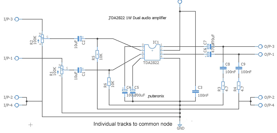
When designing a PCB or wiring a circuit, make sure all signal references have an individual trace back to the common node or ground. When you have many chips in your design, connect the common or ground pins of these chips individually to common node rather than interconnecting with them with each other and then connecting it with the common node.
Tying the signal references otherwise will have negative effects in our circuit. This will result in hum and noise in analog amplifier circuits. This also applies to wiring of input or output jacks, tone and volume controls and switches.
10) CHOOSING THE RIGHT COMPONENT:
This is one of the most challenging task every designer will come across. Many designers will stick to the parts they have used in the past in their designs or use components from the circuits they find in the internet. This might sound like a workable approach but it will be definitely not optimum, you must choose your parts as per your requirements.
To do this websites of component vendors like Mouser, Digikey, Arrow, Avnet etc will be of great help. Almost all the websites have advance part search index where can find parts based on their characteristics. The options listed can be quite overwhelming but ultimately it will do the job.
You will get to refine the search with specifications like package, electrical characteristics, dimensions, cost which will fit your requirement and you will ultimately find the best suited part as per your circuit design.
FINAL WORDS:
I want to thank Ron Hoffman, Jennifer and Vlad for sharing their inputs which helped me in writing this article. The above 10 tips are very few and am quite sure there are plenty of handy tips from other fellow designers. Please share it us via the comment box below, am happy to add them in the article as well. Hope this article would have helped you with circuit designing, looking forward to hear your thoughts and suggestions.