Random number generators are fun circuits that has applications in games, lottery and so on. While most of the number generators are based on MCU, I thought to build it only using a 555 timer and IC 4026 along with a common cathode 7 segment display. It’s quite simple and easy to build more than that it is cost effective.
HOW IT WORKS:
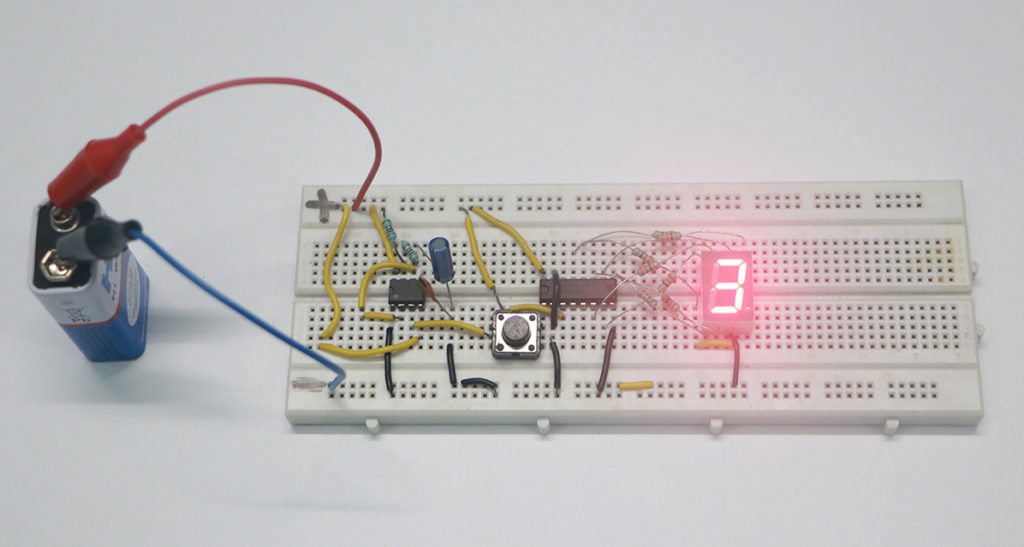
In this circuit the user is given a push button SW1 where it needs to be pressed for the number sequence to start. The number count goes from 0 to 9, with few modifications this circuit can be built to count from 0 to 99. When the button is pressed the circuit will increment the sequence at high speed and upon the release of this button you will have your random number.
PARTS USED:
1) IC 555
2) IC 4026
3) Common cathode 7 segment display
4) Resistors – 300 Ohms (7) and 1k (2)
5) Capacitors – 1uF
WORKING OF RANDOM NUMBER GENERATOR CIRCUIT:
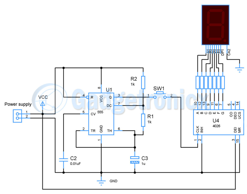
In this circuit 555 timer is wired as astable multivibrator where it generates square waves to feed the IC 4026. The frequency of this square wave depends upon the value of R1,R2 and C1. The formula to determine the output frequency is f = 1.44 / ( R2 + 2R1 ) C1 which gives a square wave of frequency 480hz as output.
You should keep the frequency output high so that the user will cannot judge the number sequence by any means. A button is placed in way of this signal which is feed to the IC 4026 when button is pressed. IC 4026 is a 7 segment decoder which takes clock signal input. The IC counts from 0 to 9 with each individual clock pulse and resets back to 0 once it hits 9. This cycle repeats itself with the incoming clock signal. The chip also decodes these counted values of 0 to 9 and lights up the 7 segment accordingly.
Since the speed of the clock signal is too fast the IC will count from 0 to 9 almost 48 times ( due to 480 hz clock signal ) in a matter of second. This makes the number appears in the 7 segment to be random and unpredictable in nature.
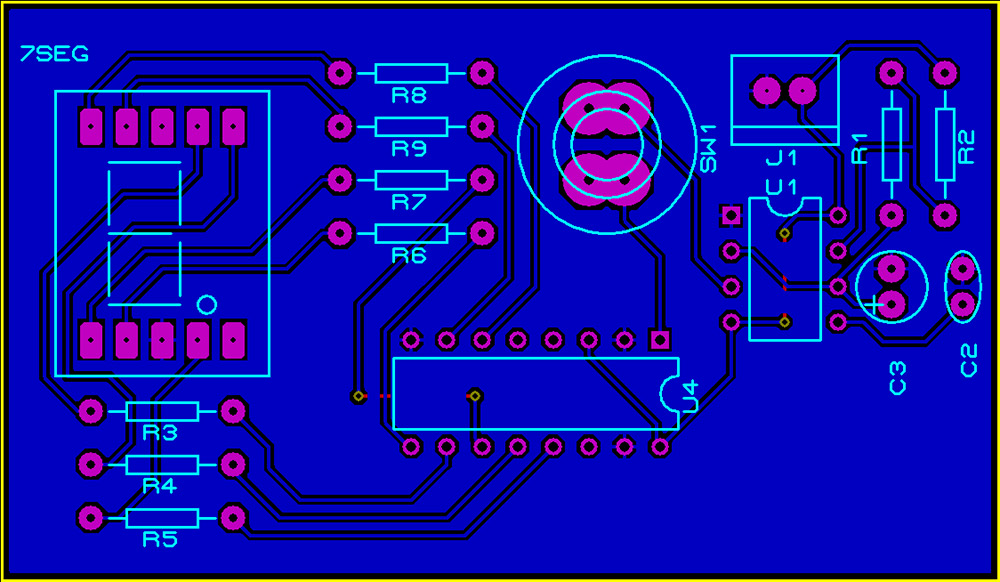
PCB design files of Random number generator circuit using IC 555 and CD4026 and 7 segment display
Author:
Frank Donald
Category:
Circuit Design Files
Date:
April 27, 2018
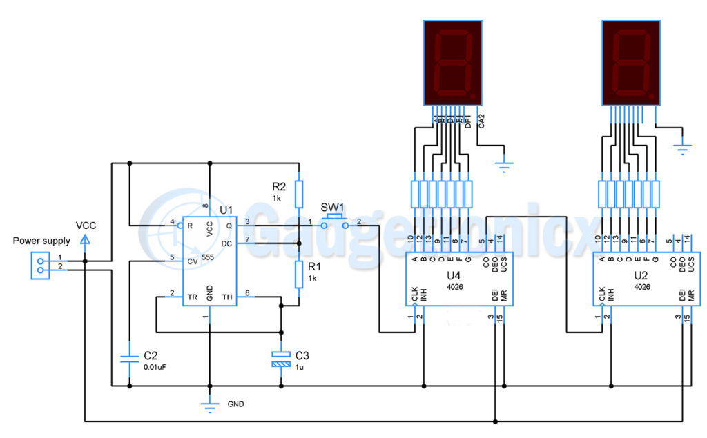
CIRCUIT TO COUNT FROM 0 TO 99:
By adding one more IC 4026 and 7 segment to the circuit you could make the circuit to count from 0 to 99. Almost all the connections remain same except you need to feed CO ( clock out ) from IC2 to IC3 Clock input. The 4026 gives out a CO signal once it reaches the count 9. Feeding this to IC3 will force it to increment one count with each cycle of counts from 0 to 9 in IC2. Therefore these two IC’s work together to count from 0 to 99.
Hope this circuit was useful to you. Do post your comments, suggestions and thoughts about this circuit in the below comment box. Happy DIY 🙂
I need help on how to make the circuit skip a count when the button is pressed, meaning the display show no number when pressed once but show number 1 when pressed second time. then after that when pressed again display stays at 1 and when pressed again show number 2 and so on. the circuit counts when button is pressed twice.
While I was reading about devices to salvage electronic from I started to look at things that weren’t mentioned, nowadays there has been an explosion of “smart devices “ and rechargeable power tools as well as old cellphones although I think they were added. What sorts of things can be had from those. I am just a beginner and not familiar with theses thing yet, however; I am a great salvager.
P. Scaia.


I need help on how to make the circuit skip a count when the button is pressed, meaning the display show no number when pressed once but show number 1 when pressed second time. then after that when pressed again display stays at 1 and when pressed again show number 2 and so on. the circuit counts when button is pressed twice.
could you email me your answer please at jbarakat@primomic.com
A very interesting artical sheds light on how a centralized computer can be used to control multipal gaming machines!
Why cant I download the files?
I have registered and logged in
Same issue, were you able to download files ?
While I was reading about devices to salvage electronic from I started to look at things that weren’t mentioned, nowadays there has been an explosion of “smart devices “ and rechargeable power tools as well as old cellphones although I think they were added. What sorts of things can be had from those. I am just a beginner and not familiar with theses thing yet, however; I am a great salvager.
P. Scaia.