Boost converter is a step up converter that takes the input voltage and deliver stepped up voltage as output to the load. Recently I have designed a high power boost converter that is capable of handling high loads. Let’s go take a look at its specifications first.
SPECIFICATIONS OF BOOST CONVERTER:
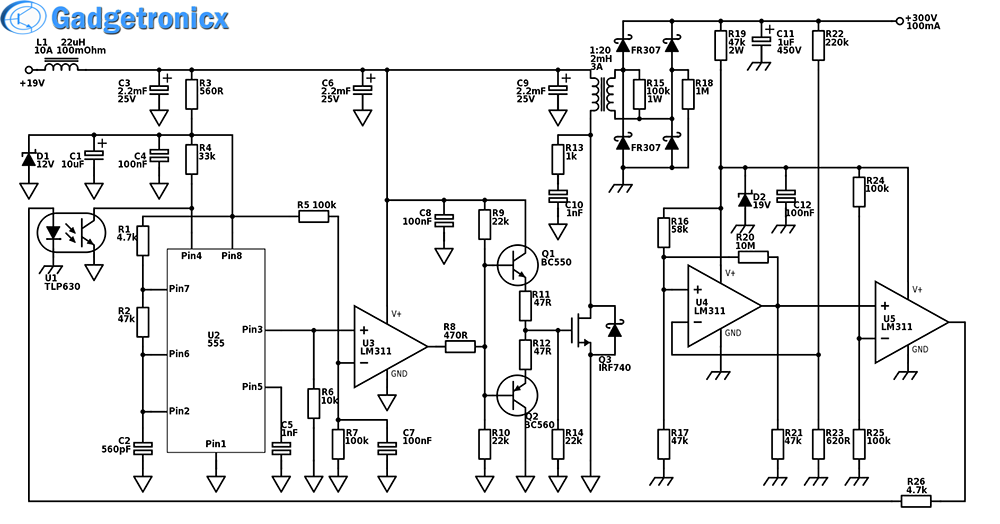
Input Voltage – 19V/5A – an old laptop supply for example
Output Voltage – 300V
Output Power – Solely dependent on how much supply current the input source can supply. A 5A/19V source can supply 95W of power. An ideal output level, would then be 300V/300mA. Since the circuit, as all others, has an efficiency value, the actual output level would be at 79% the ideal level. In this case, the output would be around 20W less than the input. All that extra power gets dissipated through the MOSFET, so keep that in mind when designing the MOSFETs heat sink.
Efficiency – 79%, which is as high as they come. Rarely you can find a better efficiency rating.
Output Voltage – This circuit will work with a fixed output. But tweaking the value of R23 SLIGHTLY will give you a different output voltage.
Output ripple – 0.003%/V . The ripple is of high frequency. For greater stability, add a linear regulator after the converter.
Ripple rejection – No AC ripple exist on the output, because of the galvanic separation at the input.
WORKING OF BOOST CONVERTER:
Have you notice the different ground symbols on different parts of our boost converter circuit? No, that is not a mistake. The switching part of the circuit is galvanically separated from the output. That is mostly because the MOSFET, during its short conduction angles, will conduct heavy currents into the ground rail. Typically, the ground rail is not good for sinking such amounts of current, and will raise the zero volts ground potential.
This is a perfect opportunity for the RF noise to find its way into the output. By using the RF transformer, you can effectively separate the ground rails of the two parts of the circuit. Such a transformer should be hand wound on an air core by using thick wire as the primary, and thinner wire for the secondary. RF transformers typically need some tricks in order to work correctly, but there is a great extend of literature on the subject, so ill leave it to you to find out how to wind the transformer. What may work for me, might not work for you.
Anyway the galvanic separation potentially causes problems with the servo loop controlling the output voltage. That’s where the most important part of the circuit (the optocoupler) comes into play. Since the output is electrically separated from the input, the servo loop needs a different kind of carrier to command the input. There are a few choices actually, but this one seems to be the best, when it comes to speed of operation and simplicity.
555 TIMER:
The heart of the circuit is the 555 timer. Its primary purpose is to generate the high frequency pulses, that will operate the MOSFET – the main switching device. Since a constant train of pulses would result in an unstable output with load variations, the servo loop controls pulse duration and frequency of the timer in accordance to the output voltage vs. load. A heavier load, causes the MOSFET to switch slower, thus inducing higher magnetic field in the RF transformer, which in turn causes the output to generate more energetic pulses to maintain the output voltage steady.
The input filtering is ESSENTIAL because during the first ms or so, there is no output voltage and the RF transformer struggles to raise the voltage to the given potential. This creates almost a short circuit in the first moments, with peak currents of over 50A. An input filter, with high enough capacitive reservoir will resist the huge current drain from being sourced directly from the power supply, but rather, from the stored energy from the capacitors. The input choke, further reduces the current drain, as an inductor typically inhibits abrupt current changes through it.
STABILITY MEASUREMENTS:
Stability measurements have been taken on a few considerations. The first one is self resonance of the RF transformer. The R13/C10 RC chain is used to quench any high frequency ringing at the primary of the transformer. The R15 resistor has a similar purpose on the output of the transformer. When the output is left without a load. the transformer may begin ringing, because it will be left unloaded. The R15 resistor, imposes a constant load on the secondary, thus critically dampening any stray oscillations that the transformer may produce.
Another important measurement will be with R20 resistor. You may want to experiment with the value somewhat, in order to get the best stability. This resistor causes the respective comparator U4 to have a slight hysteresis in its characteristic, thus separating the output voltage threshold into two distinct levels. If not for the hysteresis the output will swing around a single voltage, and once loaded with a heavier load, the oscillations may become critically dampened at the given frequency, The circuit will try to compromise by raising the frequency, but sooner or later things will get out of hand and the whole thing will die out miserably. Worst case scenario, the MOSFET becomes permanently ON, and there will be a short in input.
Hope everyone will try this circuit out, please let me know the outcome if you do. Post in the below comment box if you have any queries and I will try to help you out.
Hi, just wanted to say, i didnt manage to make feedback working,R19 was heating a lot, and i didnt get how lm311 is supposed to drive optocoupler if it cant send logic one,only 0 or leave output floating. And i think you should swap R1 and R2.
Hey Vladislav, nice circuit of yours. But I’ve got a simpler question about boost converters no one on Internet has answered yet, if one did it I’ve not found, and I have truly searched a lot Ahahahhaha
The question is: what’s the physical explanation to the behavior of an bigger or smaller inductor(in size itself) in a boost converter? Because essentially I’ve discovered by working my circuits that generally high frequency boost’s ckts need larger inductors though I don’t understand why is that. If you could reply, I’d be glad. Thank you and nice circuit, and great idea by separating grounds.
Yeah, the value of the inductor depends on the design. One consideration is how much current will it need to handle. A 10A coil will not use the same wire size as a 1A coil. Also as you may know inductors are frequency dependent components, restricting the current flow at higher frequencies, and passing lower frequencies. So depending on the frequency in use, and the desired current through the coil, the inductance will vary greatly and with it the winding turns on the former. Size is directly proportional to needed inductance (and whether the core is solenoid or air) and the current which the coil must handle
Thank you Vladislav, I didn´t consider frequency effects in the inductor when I was analysing, which was an terrible error of mine. Now I have clarified my understanding, thank you very much and keep up with the good work!