 |
| Temperature Controlled DC motor |
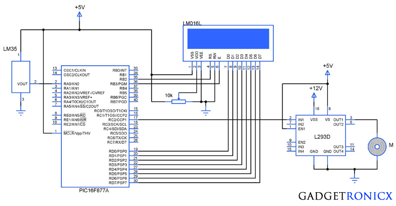
You might have come across several applications where we need to control a specific device based on analog parameter. This Embedded system works in a similar concept where we are about to control the speed of a DC motor using based on the external temperature. The rise in temperature will result in increase in speed of the motor and vice versa. These type of Temperature controlled fan systems can generally be used to maintain temperature of a room or object automatically.
DESIGN OF TEMPERATURE CONTROLLED FAN SYSTEM:
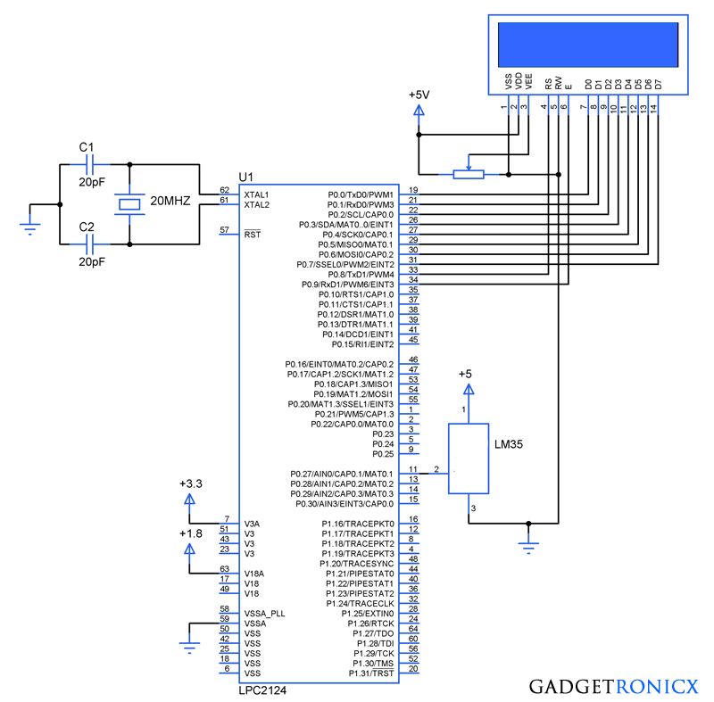
- The temperature is measured by means of a temperature sensor LM35.
- The output voltage of the sensor is fed to the A/D channel of the Microcontroller.
- Based on the sensed temperature the speed of the motor is controlled using PWM .
- Several temperature ranges was set in the code to vary the motor speed based on the level of temperature sensed.
- The speed of the motor is controlled by using PWM.
- The motor is driven using a driver IC l293D, See a brief explanation on its working and wiring here.
LM35:
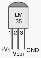 |
| LM35 Pin Diagram |
Lm 35 is used to sense the external temperature which is capable of sensing temperature ranges from -55 to 150 C. The output voltage is proportional to the temperature hence there is no need of trimmers to calibrate the reading. The output voltage of this sensor varies by 10mv per degree change in temperature.
CALIBRATION:
We are using a 10 bit ADC and Vcc as Vref to the ADC module of the Controller. So in order to determine the step size we have to divide the Vref by our resolution that is 2^10 ( 1024 ).
Step Size = 5 / 1024 = 4.83mV
We obtain a change of 10mV with each rise or fall in temperature from the sensor. And value in the ADC register will alter by two steps with each degree change in the sensor since two increments of step size i.e 4.833mV * 2 = 9.96mV which is approximately equal to 10mV. So in order to obtain the original value we have to divide the contents in the ADC register by 2
Real value = ADC value / 2
CODE:
This code was built using CCS compiler for PIC Microcontrollers.
#include <16F877A.h>
#device ADC=10                              //Setting ADC bits
#FUSES NOWDT
#FUSES NOBROWNOUT
#FUSES NOLVP
#use delay(crystal=20000000)
#byte lcd=0x08
#byte TRIS_lcd=0x88
#bit rs=0x06.2
#bit en=0x06.3
#bit TRIS_rs=0x86.2
#bit TRIS_en=0x86.3
long int adc_value,real_value;
int i;
char value[4];
unsigned char text[]="Temperature:";
void display(unsigned char a, int b);
void motor();
void main()
{
  TRIS_lcd=TRIS_rs=TRIS_en=0;
  display(0x38,0);
  display(0x01,0);
  display(0x0c,0);
    for(i=0;i<=12;i++)
    {
     display(text[i],1);
    }
  setup_timer_2(T2_DIV_BY_16,255,1);    //Setting timers for PWM
  SETUP_ADC_PORTS(AN0);                   //Setting ADC PORTS
  SET_ADC_CHANNEL(0);                       //Selecting Channel
  SETUP_ADC(ADC_CLOCK_INTERNAL);
     while(TRUE)
      {
        delay_us(20);
        adc_value=READ_ADC();            //Reading ADC value
        delay_us(10);
        real_value=adc_value/2;           //Obtaining real value
        motor();
        sprintf(value,"%lu",real_value);  //Changing int to char
        display(0x8c,0);
          for(i=0;i<=3;i++)
           {
             display(value[i],1);
           }
      }
 }
void display(unsigned char a,int b)         //LCD sub routine
  {
    lcd=a;
    rs=b;
    en=1;
    delay_ms(10);
    en=0;
    delay_ms(10);
  }

void motor()
{
  if(real_value<10)
   {
   setup_ccp1(CCP_OFF);
   }
  if(real_value>10)
   {
     setup_ccp1(CCP_PWM);
      if(real_value>=10&&real_value<=29)
      {
        set_pwm1_duty((int16)204);         //20% duty cycle PWM
      }
      else if(real_value>=30&&real_value<=69)
     {
       set_pwm1_duty((int16)510);         //50% duty cycle PWM
      }
      else if(real_value>=70&&real_value<=99)
      {
         set_pwm1_duty((int16)715);      //70% duty cycle PWM
       }
      else if(real_value>=100&&real_value<=150)
       {
         set_pwm1_duty((int16)919);     //90% duty cycle PWM
       }
    }
 }
The above code uses built in functions in the CCS compiler to use the A/D and PWM feature in the Microcontroller. The received analog value is calibrated to display the temperature in the LCD. The “real_value” int value is converted to character using “sprintf” in order to display the temperature values.
The temperature ranges and duty cycle of the PWM is given using the subroutine “.motor”. So the microcontroller runs a check on the temperature every time and alters the speed of the motor based on it.

what LCD did you use 16*2 ?
Hi Melric,
Yes it was 16×2 LCD
I have some problems there’s no display in LCD when I turn on the powersupply the LCD will display a block of dots and after a few seconds it will disappear and there’s no display . I dont connect the Motor driver because I want to see only the display first did you think this will affect ? and I dont sure if program is written already in the Microcontroller
Melric,
Check your LCD connection with MCU also try adjusting the contrast of LCD with a POT, you might get something.
sir can I ask what type of petentiometer did you used because when I try to run again the circuit there’s no display in the LCD
sir I have a problem because when I use a adjustable 24v power supply and I adjust it on 5v when i supply it on the circuits it turns to be 3.4v did you know what is the problem and I use a potentiometer but when I look at youtube they are all using bourn trimmer to adjust the contrast. sir can you email to me the picture of potentiometer that you use ?
Melric,
I believe that your power supply bends when load is connected. A optimum power supply will not bend or shows less bending when load is connected. In your case its pretty high try any other power supply and see if it fixes the problem. This is what i use
http://i.ebayimg.com/00/s/NTAwWDUwMA==/z/GwAAAMXQyY1TVg~U/$_3.JPG?set_id=2
Sir what specs of DC fan can I use that fits to L293D
and what is a 10k on the connection is it a potentiometer ?
Hi Melric,
The DC fan is capable of handling DC motors rated from 4.5v to 36v. Anything motors that lies within this voltage rating won’t be a problem for L293D. Yes it was a potentiometer used to adjust contrast of LCD
I use potentiometer but it doesn’t work. there is no character dsiplayed in LCD but I saw on the internet that they use rheostat instead
Melric,
I think Rheostat is overkill. Potentiometer will do fine, check if all the connections are right. You will see black boxes when you adjust the pot, anything like that.
Sir can I use ordinary dc fan ?
Hi Melric,
Yes you can use a ordinary DC fan. But make sure you can provide enough current to drive the fan since MCU output current will be too low to handle them.
Sir where I can download the CCS compiler and how to insert the code to the Microcontroller
Melric,
Here is the download link http://www.ccsinfo.com/ccsfreedemo.php
Please e-mail me the hex file. I can’t get it to work properly. I need this to complete my project final year . My e-mail is amyrulmuhd55@gmail.com
Can I use a PIC16F876A instead of a PIC16F877 and just change the ports to ABC instead of ADC?
Please e-mail me the hex file. I can’t get it to work properly. I need this to cool a power supply. My e-mail is imalan54@yahoo.com Thanks